Toner container and toner supply device unit using the same

a technology of toner container and supply device, which is applied in the direction of instruments, electrographic process equipment, optics, etc., can solve the problems of adverse influence on operation and maintenance performance, and achieve the effects of reliably peeling the sealing element, good sliding ability, and preventing the operation of the toner container body and peripheral parts from being hindered

Inactive Publication Date: 2007-07-26
SHARP KK
View PDF4 Cites 28 Cited by
  • Summary
  • Abstract
  • Description
  • Claims
  • Application Information

AI Technical Summary

Benefits of technology

[0030]According to the seventh aspect of the invention, since the sealing element is formed of a material having air-permeability, this configuration, in addition to the effect achieved by any one of the first to sixth aspects of the invention, makes it possible to store toner in a stable condition without causing any deformation of the toner container and any toner leakage even when there occurs a pressure difference between the interior and exterior of the toner container due to change in air pressure or the like.
[0031]According to the eighth aspect of the invention, since the sealing element is formed of a material having good slidability, this configuration, in addition to the effect achieved by any one of the first to seventh aspects of the invention, makes it possible to prevent the operations of the toner container body and peripheral parts from being hindered even if the sealing element is separated from the toner container body.
[0032]According to the ninth aspect of the invention, since the sealing element is formed in a shape covering an angular range of 180 degrees with respect to the peripheral direction of the toner container body, this configuration, in addition to the effect achieved by any one of the first to eighth aspects of the invention, makes it possible to prevent the sealing element, even if it is separated from the toner container body, from blocking the toner discharge port when the port is located at the predetermined position, hence discharge toner properly.
[0033]According to the tenth aspect of the invention, since the adhesive strength with which the sealing element is fixed to the toner container holder is specified to be greater than the adhesive strength with which the sealing element seals the toner discharge port of the toner container body, this configuration, in addition to the effect achieved by any one of the third to sixth aspects of the invention, makes it possible to open the toner discharge port by reliably peeling the sealing element off the toner container body.
[0034]According to the eleventh aspect of the invention, since the sealing element after separated from the toner container body remains inside the toner container holder with one end thereof fixed to the toner container holder, this configuration, in addition to the effect achieved by any one of the third to sixth and tenth aspects of the invention, facilitates simple breaking of the seal without the necessity of waste disposal of the sealing element that has been removed from the toner container body.
[0035]According to the twelfth aspect of the invention, since in a toner supply device including: a toner container filled with toner; and a toner feed device having the toner container mounted thereon for feeding the toner discharged from the toner container to a developing unit, the toner container uses a toner container described in any one of the above first to eleventh aspects, this configuration facilitates mounting of the toner container into the machine without causing any spill of toner and makes it possible to easily open the toner discharge port by peeling the sealing element by rotation of the toner container which has been fitted in the machine. As a result it is possible to provide a toner supply device which is markedly improved in the operativity and maintenance performance without making the operator and the machine dirty with spilt toner.

Problems solved by technology

However, in the above-mentioned prior art, when the toner cartridge is mounted to the toner supply device, there is a fear that toner spills out and falls from the toner discharge port formed in the toner cartridge, causing the harmful problem of dirtying the operator and the machine with the spilt toner, hence producing adverse influence on the operativity and maintenance performance.

Method used


Image

  • Toner container and toner supply device unit using the same
  • Toner container and toner supply device unit using the same
  • Toner container and toner supply device unit using the same

Examples


Embodiment Construction

[0066]The best mode for carrying out the present invention will be described with reference to the drawings.

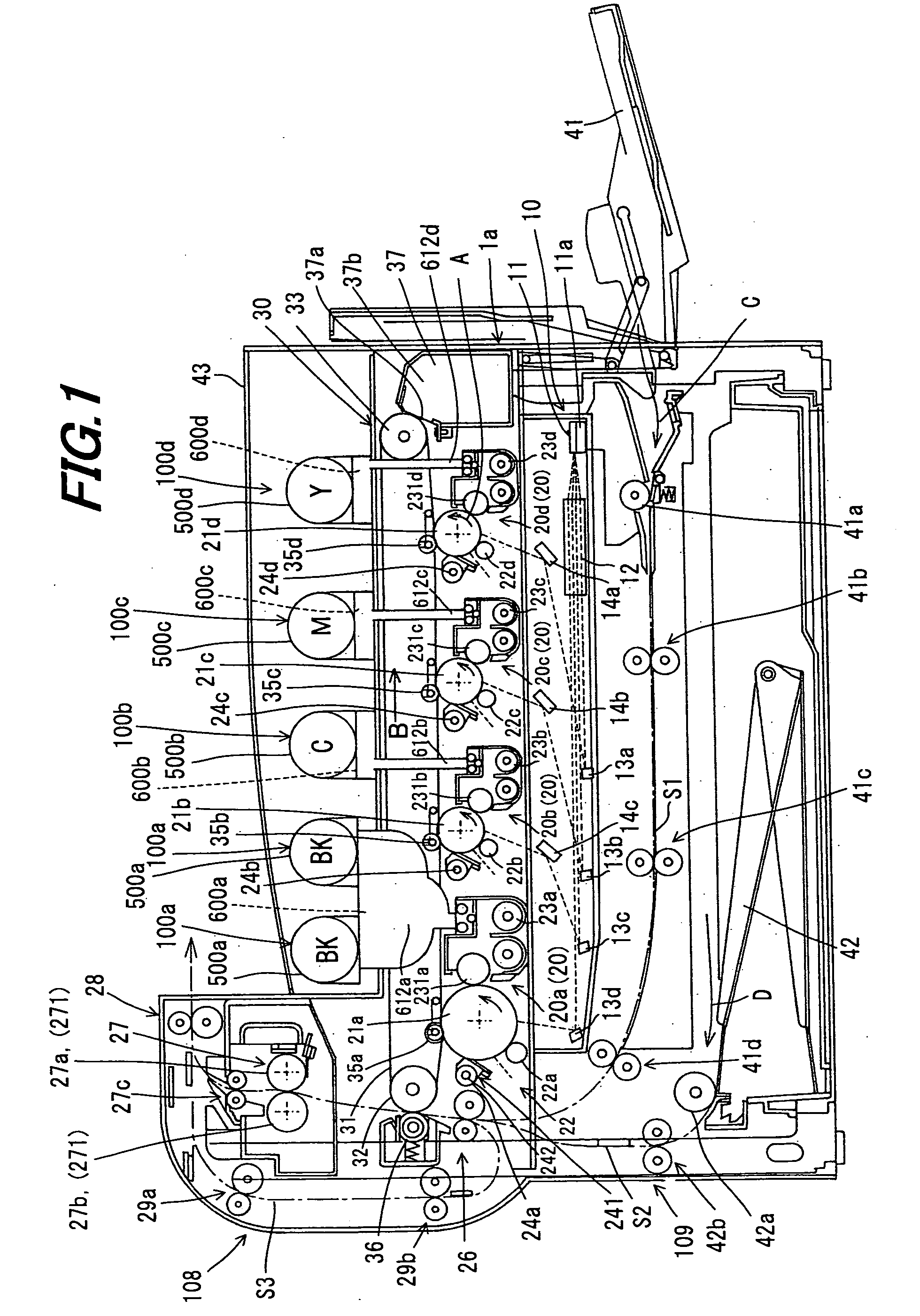
[0067]FIG. 1 is an example of the mode for carrying out the present invention, and is an illustrative view showing an overall configuration of an image forming apparatus adopting a toner container according to the present invention.

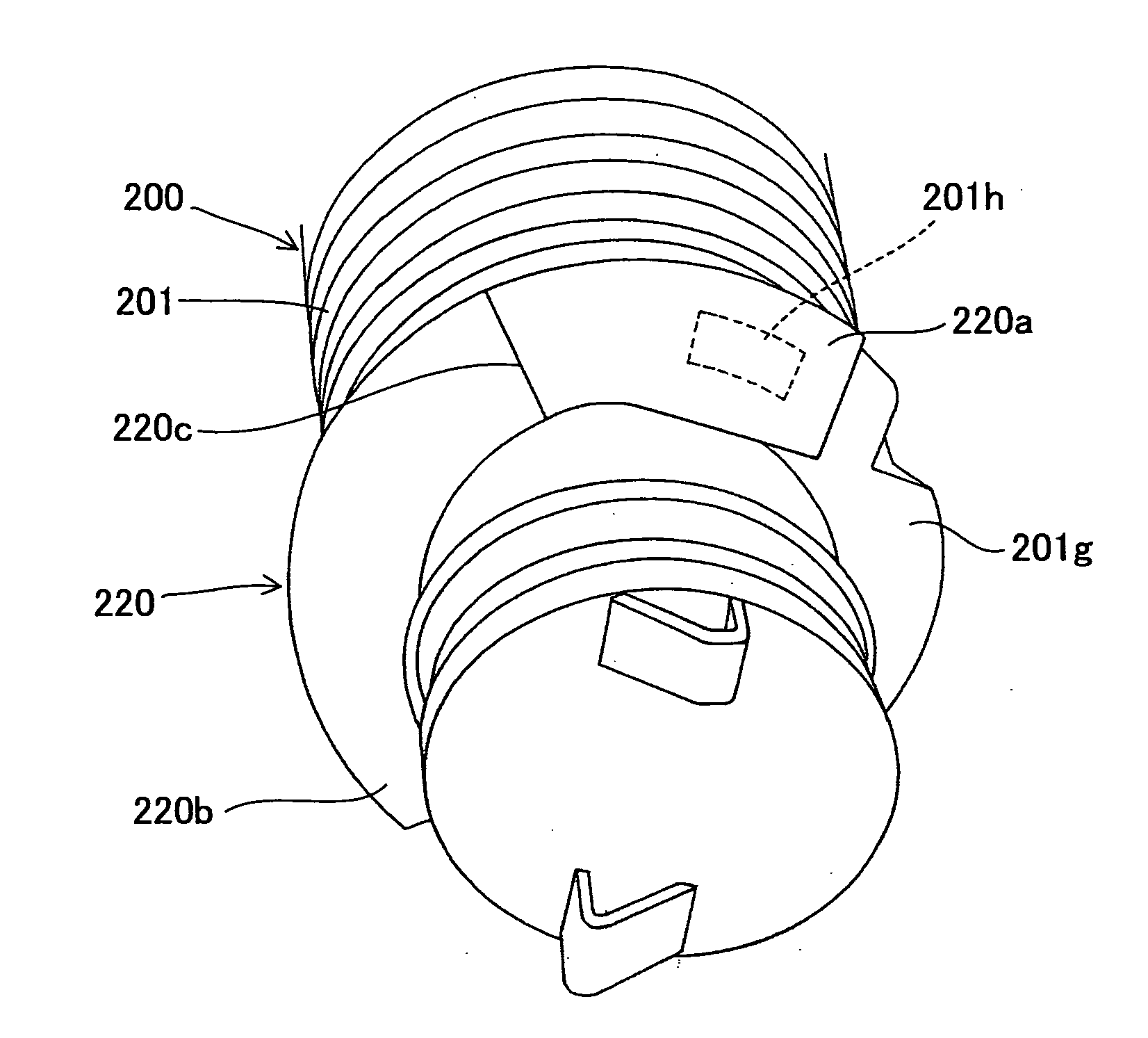
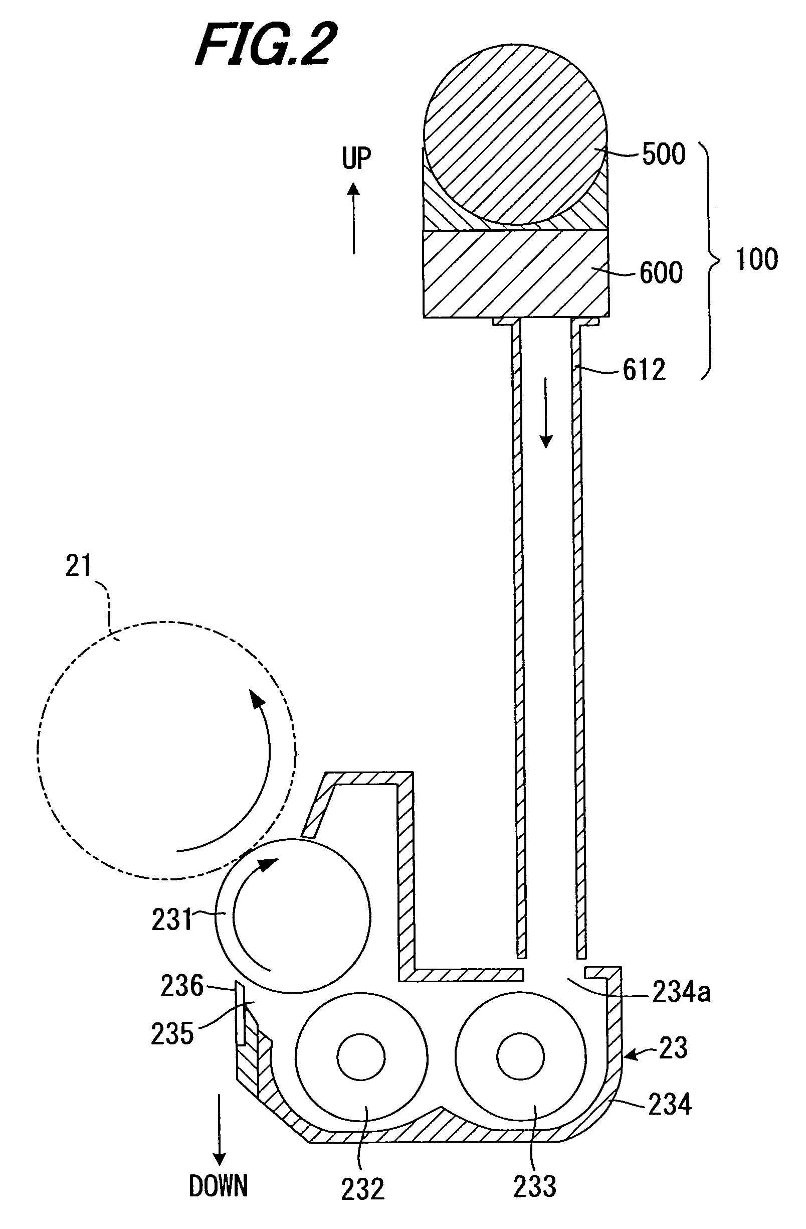
[0068]As shown in FIG. 1, the present embodiment is applied to an image forming apparatus 1 in which developer images formed on photoreceptor drums 21 (21a, 21b, 21c and 21d) with developers (toners) which are supplied from developing rollers 231 (231a, 231b, 231c and 231d) in accordance with image data are transferred to a recording sheet by a transfer process, and includes toner supply devices 100 (100a, 100b, 100c and 100d) each having a toner bottle (toner container) 200 (200a, 200b, 200c or 200d: FIG. 3) for supplying toner to developing units 23 (23a, 23b, 23c and 23d) so as to perform image output by automatic toner supply to the developing u...


PUM


Abstract

A toner bottle that is composed of a main body filled with toner and a bottle-side toner discharges port for discharging toner from the main body is adapted to discharge the toner in the main body out of the container whilst the toner bottle is being rotated in the toner bottle's peripheral direction. The toner bottle has a sealing element that seals the bottle-side toner discharge port. This sealing element is formed of a flexible member, and is peeled off the main body of the toner bottle as the toner bottle is rotated so as to open the bottle-side toner discharge port.

Description

[0001]This Nonprovisional application claims priority under 35 U.S.C. §119(a) on Patent Application No. 2006-15439 filed in Japan on 24 Jan. 2006, the entire contents of which are hereby incorporated by reference.BACKGROUND OF THE INVENTION[0002](1) Field of the Invention[0003]The present invention relates to a toner container and a toner supply device using this, in particular relating to a container and a toner supply device using this for use in an image forming apparatus for performing image forming with toner.[0004](2) Description of the Prior Art[0005]Conventionally, in image forming apparatuses using toner, such as copiers, facsimile machines, etc., a toner supply device using a toner cartridge etc., is used to supply toner to the developing unit to thereby achieve continuous operation of image output.[0006]Examples of generally known methods for supplying toner to the developing unit include: a configuration in which toner stored in a toner cartridge is directly supplied to ...

Claims


Application Information

Patent Timeline
Patent Type & Authority Applications(United States)
IPC IPC(8): G03G15/08
CPCG03G2215/0668G03G15/0882G03G15/0872
Inventor KOYAMA, KAZUYADEGUCHI, MASANOBU
Owner SHARP KK
Why Eureka
Try Eureka