Tape printer

a printer and tape technology, applied in the field of tape printers, can solve the problems of damage to tape and/or ink ribbon during storage and use, etc., and achieve the effect of high quality printing

Inactive Publication Date: 2007-07-26
DYMO (BVBA)
View PDF20 Cites 96 Cited by
  • Summary
  • Abstract
  • Description
  • Claims
  • Application Information

AI Technical Summary

Benefits of technology

[0015] Embodiments of the present invention solve the above identified problems by providing a tape printer for use with a tape cassette and an ink ribbon cassette, in which the tape cassette and ink ribbon cassette are laterally insertable into the printer in a direction which is perpendicular to an axis of rotation of a platen and a line of print elements on a printhead within the printer. Accordingly, embodiments provide a D2-type system in which the tape cassette and ink ribbon cassette are loadable into the printer without the possibility of the tape and ink ribbon catching on elements of the printer such as the printhead and / or platen. Embodiments of the present invention are user friendly and allow easy loading and unloading of cassettes into a tape printer. Furthermore, embodiments of the present invention have the advantage over D1-type arrangements in that the tape cassette or the ink ribbon cassette can be replaced individually according to the requirements of a user.
[0017] The two elongate guide members aid in both guiding the tape cassette into the tape printer and also aligning the tape cassette with a print head of the tape printer. The guide members also prevent movement of the cassette when inserted into the tape printer for better quality printing. The provision of an elongate guide member on opposing sides prevents rotational movement of the cassette.
[0019] Advantageously, the guide members should be adapted to prevent movement of the cassette in both vertical and horizontal directions when inserted into the tape printer. One such arrangement is provided by guide members comprising a first elongate member disposed in a plane perpendicular to the side walls of the cassette and a second elongate member disposed in a plane parallel to the side walls so as to prevent movement in both vertical and horizontal directions when the cassette is inserted in a printer. The guide members thus have a substantially T-shaped cross-section. With such an arrangement the cassette is very precisely positioned in the cassette-receiving bay relative to the print head for high quality printing.

Problems solved by technology

A disadvantage of this type of vertical loading arrangement is that the tape and / or ink ribbon may catch on elements of the printer such as the printhead and / or platen thus damaging the tape and / or ink ribbon.
Accordingly, the tape and / or ink ribbon may be damaged during storage as well as during use.
Furthermore, as the tape is not housed in a cassette it may be damaged during storage and use.

Method used


Image

  • Tape printer
  • Tape printer
  • Tape printer

Examples


first embodiment

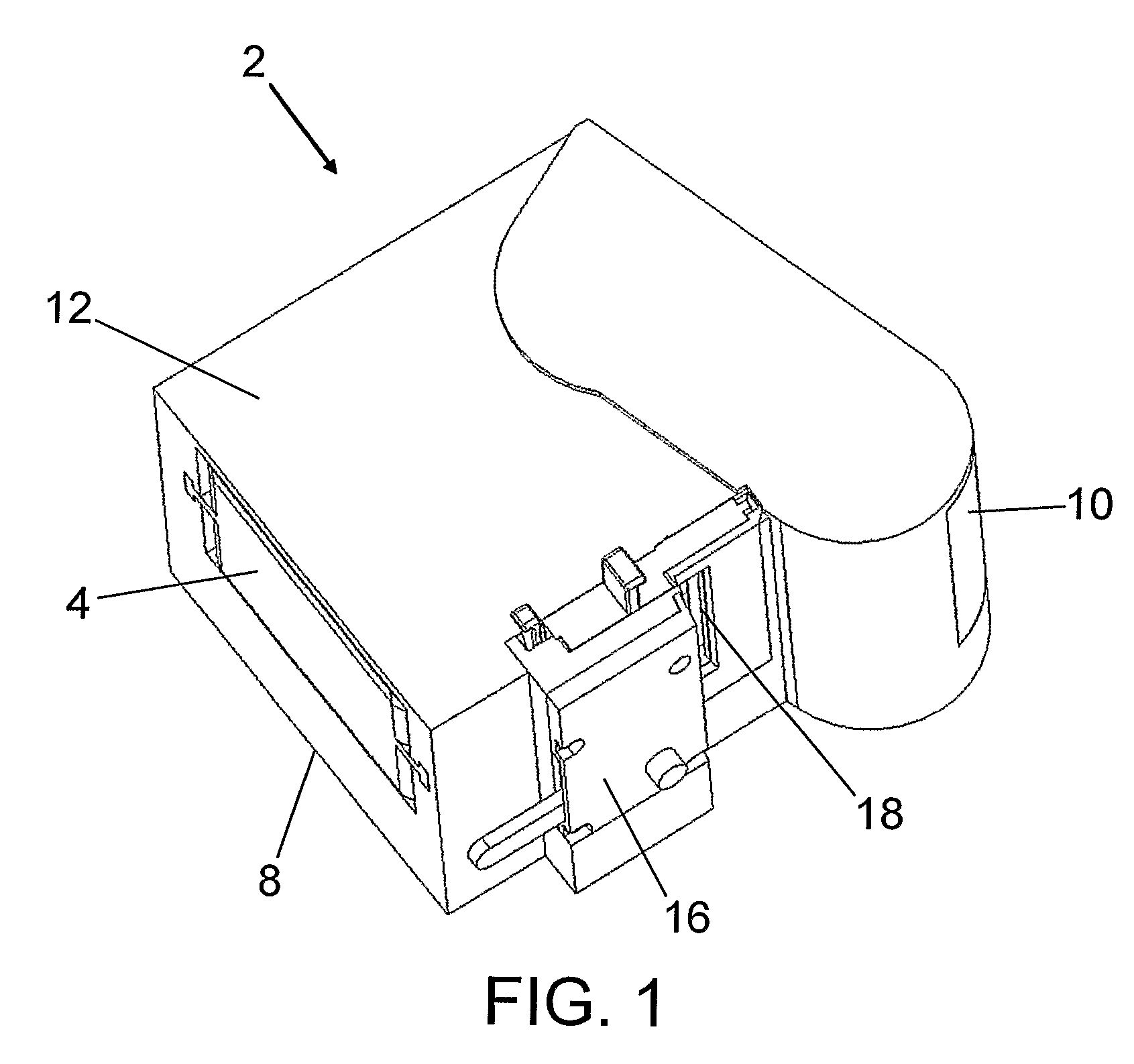
[0057] FIGS. 1 to 3 show schematic diagrams of a D2-type printing system according to the present invention. The printing system comprises a printer 2, a tape cassette 4 (an embodiment of which is illustrated in more detail in FIGS. 24 to 26 and described later) and an ink ribbon cassette 6 (an embodiment of which is illustrated in more detail in FIGS. 27 to 29 and described later). The printer 2 has a housing comprising two parts which are rotatable relative to each other. In the illustrated embodiment the housing comprises a cover 10 which is rotatable relative to a body 12 of the printer 2. The cover 10 may be a cover. An opening 8 on a side of the body 12 is provided for laterally inserting the tape cassette 4. The tape cassette 4 further comprises a platen roller 11. The cover 10 comprises a printhead 14 mounted thereon. When in an open position as illustrated in FIG. 2a, the cover 10 is arranged to receive the ink ribbon cassette 6. Closing the cover 10 having the ink ribbon c...

third embodiment

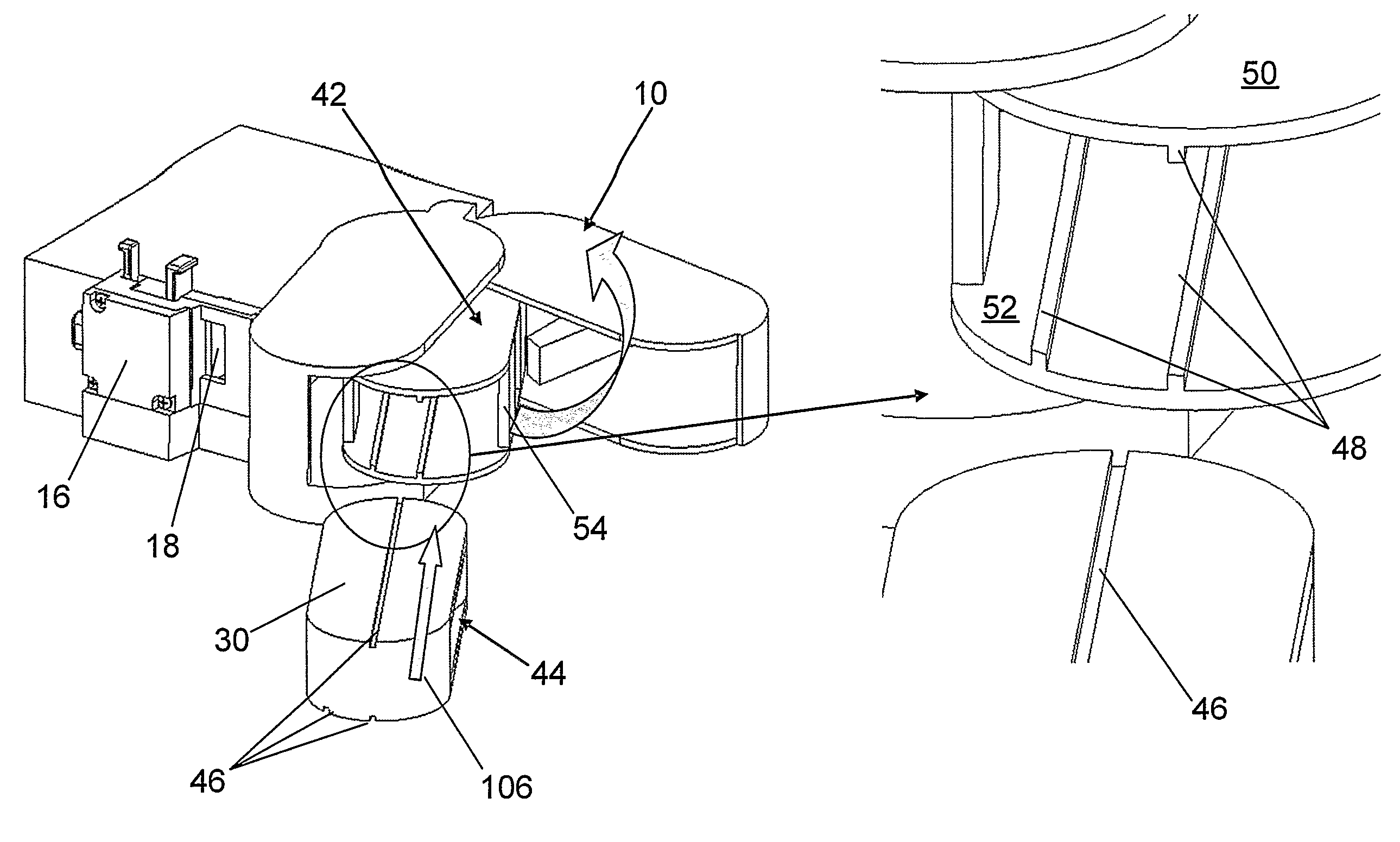
[0075] FIGS. 9 to 15 show schematic diagrams of a D2-type printing system according to the present invention. The printing system comprises a tape cassette 4, a tape printer and an ink ribbon cassette 206. The tape printer has an opening 8 in a side thereof for laterally inserting the tape cassette 4. The tape printer has another opening 58 for lateral insertion of the ink ribbon cassette 206. The tape printer further comprises a printhead 14 mounted on a rotatable mechanism 60 for rotating the printhead into a printing position via a lever 56 mounted for rotation on the printer. The printhead 14 passes through an opening in the ink ribbon cassette 206 to co-operate with the platen mounted in the tape cassette 4 such that the tape and ink ribbon are disposed therebetween.

[0076] The structure of the tape cassette 4 and the ink ribbon cassette 206 is similar to that described previously in the first and second embodiments.

[0077] The printer differs from those described in the first a...

fifth embodiment

[0085] In a fifth embodiment not illustrated, a printer may be provided with a housing comprising a single opening through which both the ink ribbon cassette and the tape cassette may be inserted. In such an arrangement, a fixed printhead may be provided in the printer. An ink ribbon cassette similar to that illustrated in FIG. 2a is loaded into the printer first in a lateral direction whereby the printhead in the printer passes through the opening in the cassette and cooperates with the ink ribbon. A tape cassette similar to that previously described is subsequently inserted through the same opening until the platen in the tape cassette cooperates with the printhead with the ink ribbon and tape disposed therebetween. In a modification of this loading procedure, the ink ribbon is partially inserted and then the tape cassette actually pushes the ink ribbon cassette into its printing position when the tape cassette is inserted. In another alternative, the ink ribbon cassette may be at...


PUM


Abstract

A tape printer for use with a tape cassette and an ink ribbon cassette, the printer comprising a housing and a printhead having a line of printing elements thereon, wherein said printer comprises at least one cassette receiving portion in said housing for receiving the tape cassette and the ink ribbon cassette, such that the cassettes are receivable in a direction which is substantially perpendicular to the line of printing elements on the printhead when the printhead is in a printing position.

Description

FIELD OF INVENTION [0001] The present invention relates to a tape printer. Particularly but not exclusively, the present invention relates to a handheld tape printer for use with a cassette housing a print receiving medium and a separate cassette housing a print forming medium, such as an image transfer tape. BACKGROUND OF THE INVENTION [0002] Known tape printers may be divided into two types: tape printers for use with a cassette which houses both a print receiving medium (hereinafter referred to as a tape which may be a continuous tape or may comprise a web carrying die cut labels) and a print forming medium (hereinafter referred to as an ink ribbon); and tape printers which are arranged for use with a cassette housing the tape and a separate cassette housing the ink ribbon. The advantage of the latter arrangement is that the ink ribbon cassette may be replaced with another cassette containing ink ribbon of either the same or a different type without replacing the tape cassette. T...

Claims


Application Information

Patent Timeline
Patent Type & Authority Applications(United States)
IPC IPC(8): B41J11/00B41J3/407B41J15/04
CPCB41J15/044B41J3/4075
Inventor VANDERMEULEN, KRIS
Owner DYMO (BVBA)
Why Eureka
Try Eureka