Rotary spindle structure

Inactive Publication Date: 2007-07-26
SMARTANT TELECOMM
View PDF8 Cites 30 Cited by
  • Summary
  • Abstract
  • Description
  • Claims
  • Application Information

AI Technical Summary

Benefits of technology

[0009]The present invention provides a rotary spindle structure, which is applied in a housing. A pair of suspended resilient butt joints is disposed on a pair of spindle lugs of the rotary spindle structure, and a spindle rod is pivotally fit in the spindle lugs. When the spindle rod is fit in the spindle lugs, both end faces of the spindle rod bear against the resilient butt joints to force the resilient butt joints to expand outwards till pivot holes of the spindle rod are snapped with protruding walls of the spindle lugs, and thus, the spindle rod is freely rotationally connected to the spindle

Problems solved by technology

However, the component elements for a conventional spindle structure are so complex that the assembling steps and the manufacturing time are increased, which results in a high cost.
Furthermore, in most cases, the rotary spindle structure is made of plastic and cannot be easily assembled and disassembled because of the poor material strength, and the rotary spindle structure will suffer from plastic deformation after a long time use, which causes the changing of the size, thereby affecting the service life.
On the contrary,

Method used


Image

  • Rotary spindle structure
  • Rotary spindle structure
  • Rotary spindle structure

Examples


Embodiment Construction

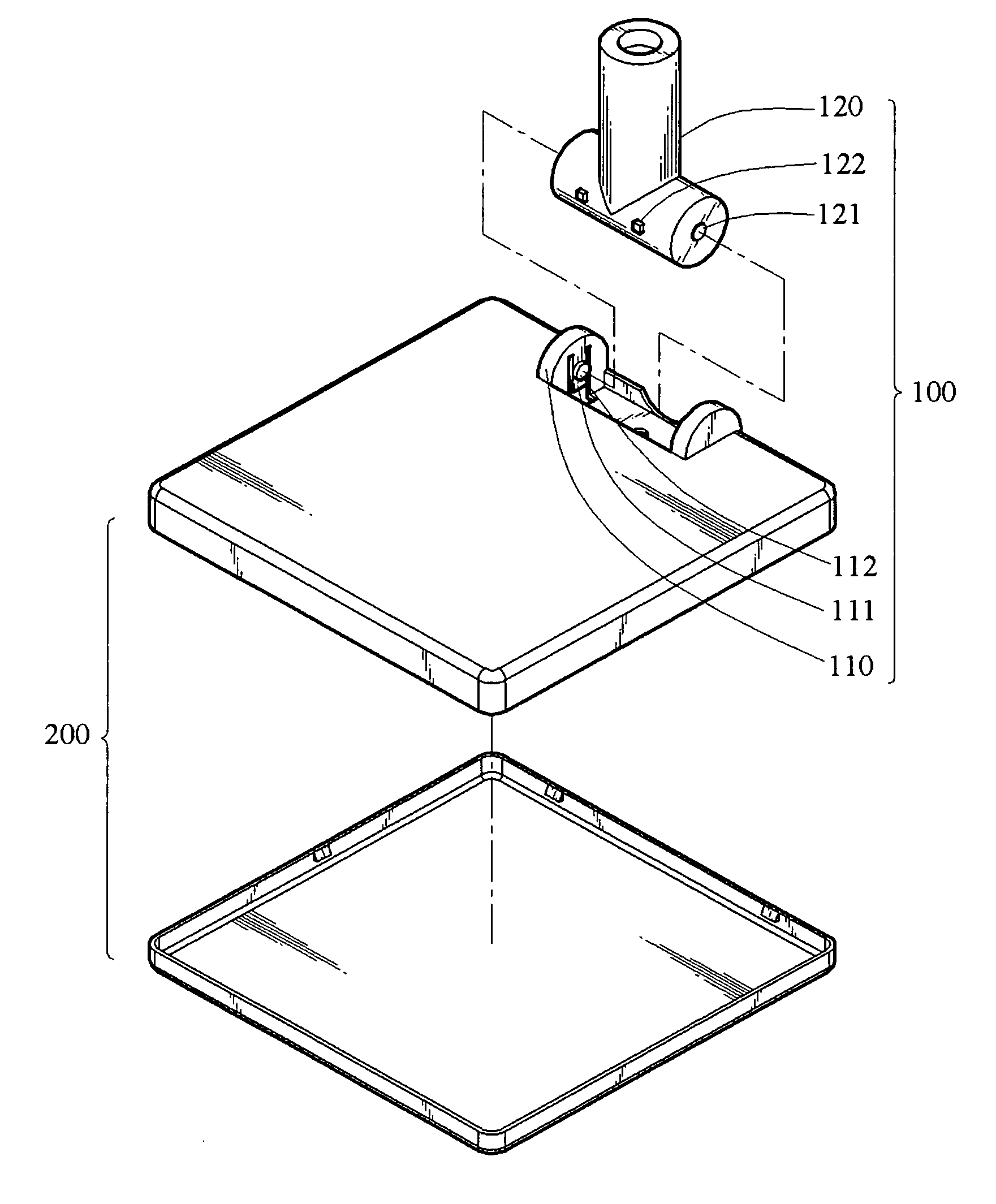
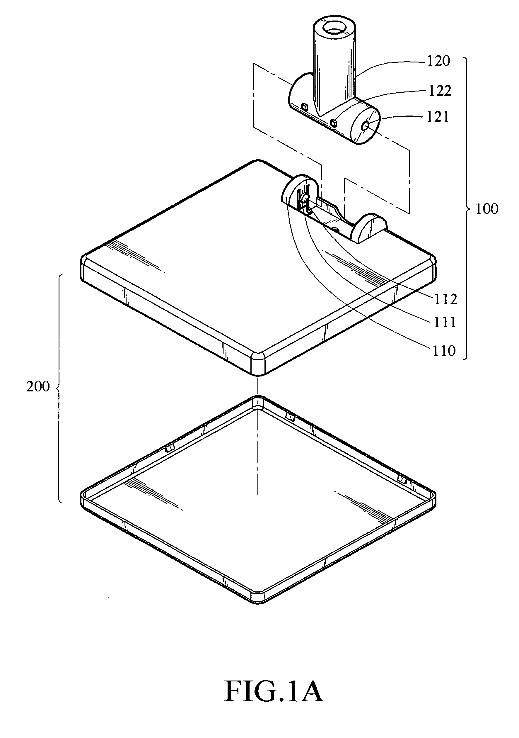
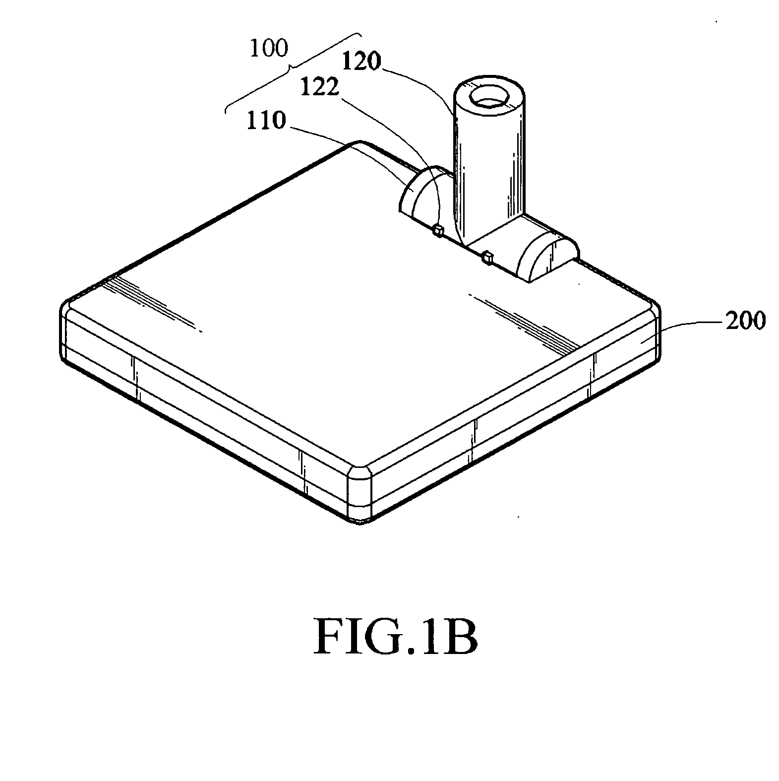
[0018]Refer to FIGS. 1A and 1B, the present invention provides a rotary spindle structure 100, which is applied in a housing 200. The rotary spindle structure 100 has a pair of spindle lugs 110 and a spindle rod 120. The spindle lugs 110 are disposed oppositely on one side of the housing 200 and spaced apart by a distance, and each of the spindle lugs 110 has a suspended resilient butt joint 111 with a corresponding protruding wall 112 respectively. The spindle rod 120 is just pivotally fit in the spindle lugs 110 and has two end faces, which are opposite to each other and have a corresponding pivot hole 121 respectively. When the spindle rod 120 is fit in the two spindle lugs 110, the two end faces of the spindle rod 120 bear against the resilient butt joints 111, so that the two resilient butt joints 111 are forced to expand outwards till their protruding walls 112 are snapped with the pivot holes 121 of the spindle rod 120, and thus, the spindle rod 120 is freely rotationally con...


PUM


Abstract

A rotary spindle structure applied in a housing is provided, which includes two spindle lugs having a suspended resilient butt joint respectively. When a spindle rod is fit in the spindle lugs, both end faces of the spindle rod bear against the resilient butt joints, so that the resilient butt joints are forced to expand outwards till a pivot hole of the spindle rod is snapped with protruding walls of the spindle lugs, and thus, the spindle rod is freely rotationally connected to the spindle lugs. Furthermore, a pair of reinforcing pads is used to bear against the resilient butt joints to enhance the joining strength between the spindle lugs and the spindle rod.

Description

CROSS-REFERENCE TO RELATED APPLICATIONS[0001]This non-provisional application claims priority under 35 U.S.C. § 119(a) on Patent Application No(s). 095201391 filed in Taiwan, R.O.C. on Jan. 20, 2006, the entire contents of which are hereby incorporated by reference.BACKGROUND OF THE INVENTION[0002]1. Field of Invention[0003]The present invention relates to a rotary spindle structure, and more particularly to a rotary spindle structure, which is easily assembled and disassembled, and not easily deformed.[0004]2. Related Art[0005]Concerning portable electronic products in the current market, due to the rapid development of electronic science and technology, wireless communication has become the mainstream of the current electronic industry, in order to transmit and exchange information more rapidly and efficiently. A directional antenna for receiving wireless signals becomes an important electronic device. In order to receive more signals with more complete contents, the antenna is de...

Claims


Application Information

Patent Timeline
IPC IPC(8): F16J1/16
CPCE05D7/1077F16M11/041F16M11/10F16M2200/08Y10T403/32861H01Q1/125H01Q1/242E05Y2900/606H01Q1/084
Inventor YANG, SHENG-HSIUNGHSUEH, MU-KUN
Owner SMARTANT TELECOMM
Why Eureka
Try Eureka