Electrosurgical generator

a generator and electrosurgical technology, applied in the field of electrosurgical generators, can solve the problems of large output voltage excursions, difficult control of energy delivery, unpredictable clinical effects, etc., and achieve the effect of reducing switching transients

Active Publication Date: 2007-07-26
GYRUS MEDICAL LTD
View PDF56 Cites 28 Cited by
  • Summary
  • Abstract
  • Description
  • Claims
  • Application Information

AI Technical Summary

Benefits of technology

[0019] The very high peak power capability of the preferred wet field generator (in excess of 1 kW) allows the impedance transition occurring at the start of a tissue cutting or vaporisation cycle to be completed very quickly since only voltages in excess of those required for arcing are delivered. This significantly reduces the delay and the unwanted coagulation effects of some prior art generators. The substantially constant voltage delivery leads to cutting or vaporisation occurring at consistent rates, regardless of changes in tissue type or engagement.
[0029] With such a generator it is possible to start arcing even under conditions of relatively low load impedance. Once an arc is established, the load impedance tends to rise, to the extent that the arcing can be maintained using a continuous RF output waveform. Improved power density is available at the active electrode for vaporisation, whilst reducing electrode erosion.
[0036] As already stated, the preferred generator has a tuned output. Indeed, good results have been obtained using a generator with a resonant output network, the load curve of the generator (i.e. the curve plotting delivered power versus load impedance) having a peak at a load impedance below 50 ohms. Delivery of peak power levels into low load impedances is aided by forming the output network as a series-resonant network comprising the series combination of an inductance and a capacitance, the output of the network being taken across the capacitance. The output may be taken to all output terminal of the generator via a coupling capacitor and, optionally, a step-up transformer from a node between the inductance and the capacitance of the series combination. Whilst it is possible, instead, to take the output from across the inductance, taking it across the capacitor has the advantage of reducing switching transients. As a further alternative, the generator may have its output terminals connected to the resonant output network so that, effectively, when a load is connected to the terminals it is connected as an impedance in series with the inductance and capacitance forming the resonant combination, e.g. between the inductance and the capacitance.

Problems solved by technology

In practice, when conducting electrosurgery, the load impedance can change over a very wide range, resulting in unpredictable clinical effects.
This has the disadvantage that rapid load impedance changes can produce large output voltage excursions.
These techniques lead to a power versus load impedance characteristic which is virtually flat over a range of impedances, but one limitation is that it is difficult to control the delivery of energy when initiating tissue cutting or vaporisation (as opposed to tissue coagulation).
Delivering too much energy can result in burns adjacent the operative site, excessive smoke, or instrument failure.
Delivering too little energy causes a significant delay and can result in unwanted tissue coagulation.
The high voltages used to achieve tissue cutting or vaporisation under varying load impedance conditions are particularly demanding of the generator when the instrument experiences a low load impedance.
Indeed, as stated above, under such conditions it is difficult reliably to initiate arcing without unwanted effects.
It has been found that operation of such instruments at high voltages tends to cause erosion of the active electrode.

Method used


Image

  • Electrosurgical generator
  • Electrosurgical generator
  • Electrosurgical generator

Examples


Embodiment Construction

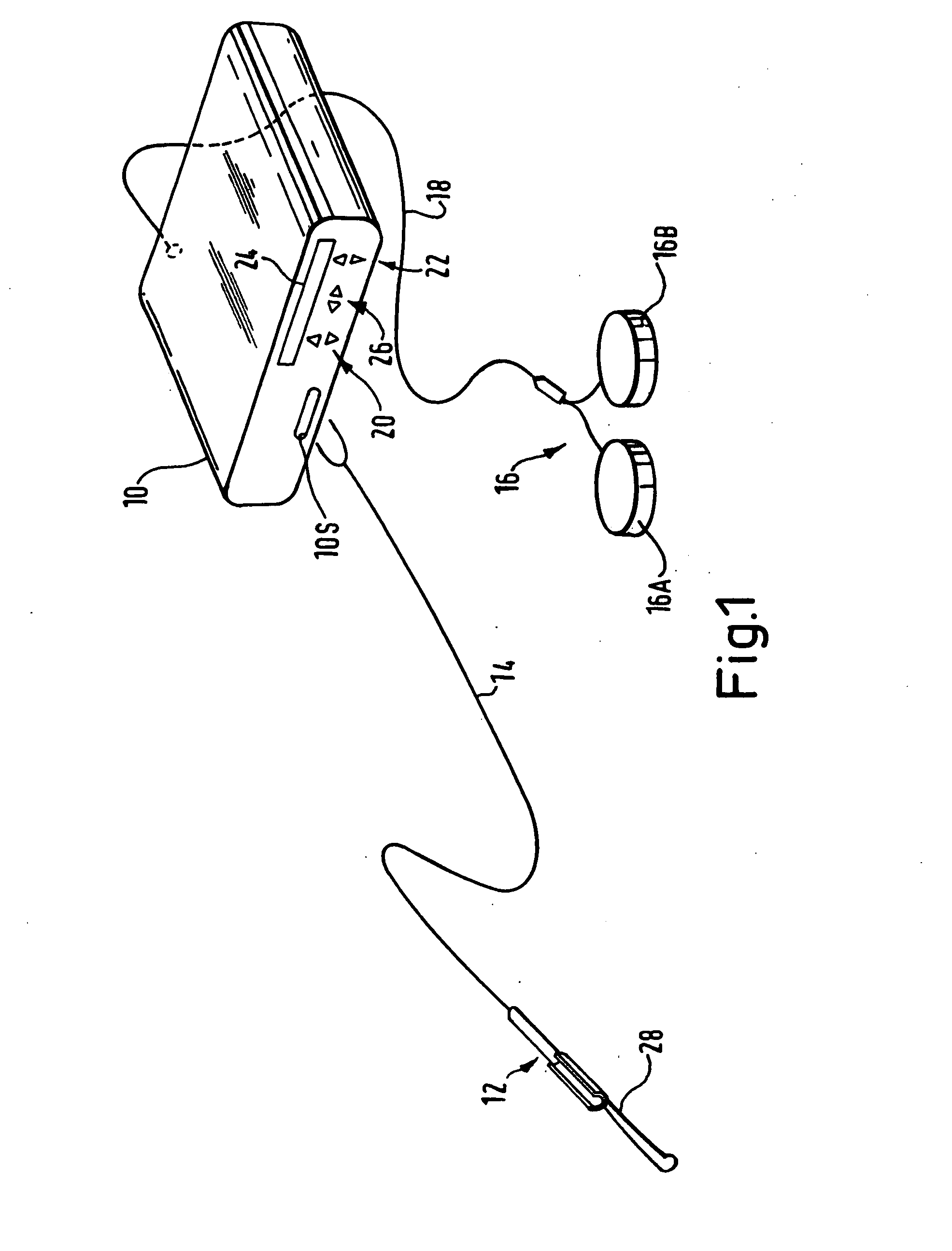
[0053] Referring to FIG. 1, a generator 10 has an output socket 10S providing a radio frequency (RF) output for an electrosurgical instrument in the form of an endoscope attachment 12 via a connection cord 14. Activation of the generator may be performed from the instrument 12 via a control connection in cord 14 or by means of a footswitch unit 16, as shown, connected separately to the rear of the generator 10 by a footswitch connection cord 18. In the illustrated embodiment, the footswitch unit 16 has two footswitches 16A and 18B for selecting a coagulation mode and a cutting mode of the generator respectively. The generator front panel has push buttons 20 and 22 for respectively setting coagulation and cutting power levels, which are indicated in a display 24. Push buttons 26 are provided as alternative means for selection between coagulation and cutting modes. The instrument 12 has a detachable loop electrode assembly 28 with a dual electrode structure and is intended for use in ...


PUM


Abstract

An electrosurgical generator for supplying RF power to an electrosurgical instrument for cutting or vaporising tissue has an RF output stage (42) with an RF power bridge (Q1, Q2, Q3, Q4), a pair of output lines (74) and a series-resonant output network (48). The output impedance of the output stage (42) at the output lines (74) is less than 200 / √P ohms, where P is the maximum continuous RF output power of the generator. The generator offers improved cutting and vaporising performance, especially in relation to the reliability with which an arc can be struck when presented with an initial low impedance load. Overloading of the output stage is prevented by rapidly operating protection circuitry responsive to a predetermined electrical condition such as a substantial short-circuit across the output lines. In the preferred embodiment, the output stage is capable of maintaining output pulses at least 1 kW peak by supplying the power bridge from a large reservoir capacitor (60). Pulsing is dynamically variable in response to load conditions by controlling the maximum energy per pulse in response to the reservoir capacitor voltage.

Description

[0001] This is a Continuation of application Ser. No. 10 / 743,095 filed Dec. 23, 2003, which claims the benefit of U.S. Provisional Application No. 60 / 449,859 filed Feb. 23, 2003 and U.S. Provisional Application No. 60 / 505,756 filed Dec. 3, 2003. The disclosure of the prior application is hereby incorporated by reference herein in its entirety.FIELD OF THE INVENTION [0002] This invention relates to an electrosurgical generator for supplying radio frequency (RF) power to an electrosurgical instrument, and primarily to a generator having a series-resonant output network. BACKGROUND OF THE INVENTION [0003] Conventionally, electrosurgical generators make use of a configuration comprising a voltage source coupled to an electrosurgical instrument via a coupling capacitor which defines a matched output impedance between 50 and 500 ohms. Such a configuration produces a power-versus-load impedance characteristic having a power maximum at a matched impedance, with power falling off progressive...

Claims


Application Information

Patent Timeline
Patent Type & Authority Applications(United States)
IPC IPC(8): A61B18/18A61B18/12A61B18/14
CPCA61B18/1206A61B18/149A61B2018/00666A61B2018/1213A61B2018/00702A61B2018/00708A61B2018/00779A61B2018/00684
Inventor GOBLE, COLIN C.O.
Owner GYRUS MEDICAL LTD
Why Eureka
Try Eureka