

Floor strip
- Summary
- Abstract
- Description
- Claims
- Application Information
AI Technical Summary
Benefits of technology
Problems solved by technology
Method used
Image

Examples
Embodiment Construction
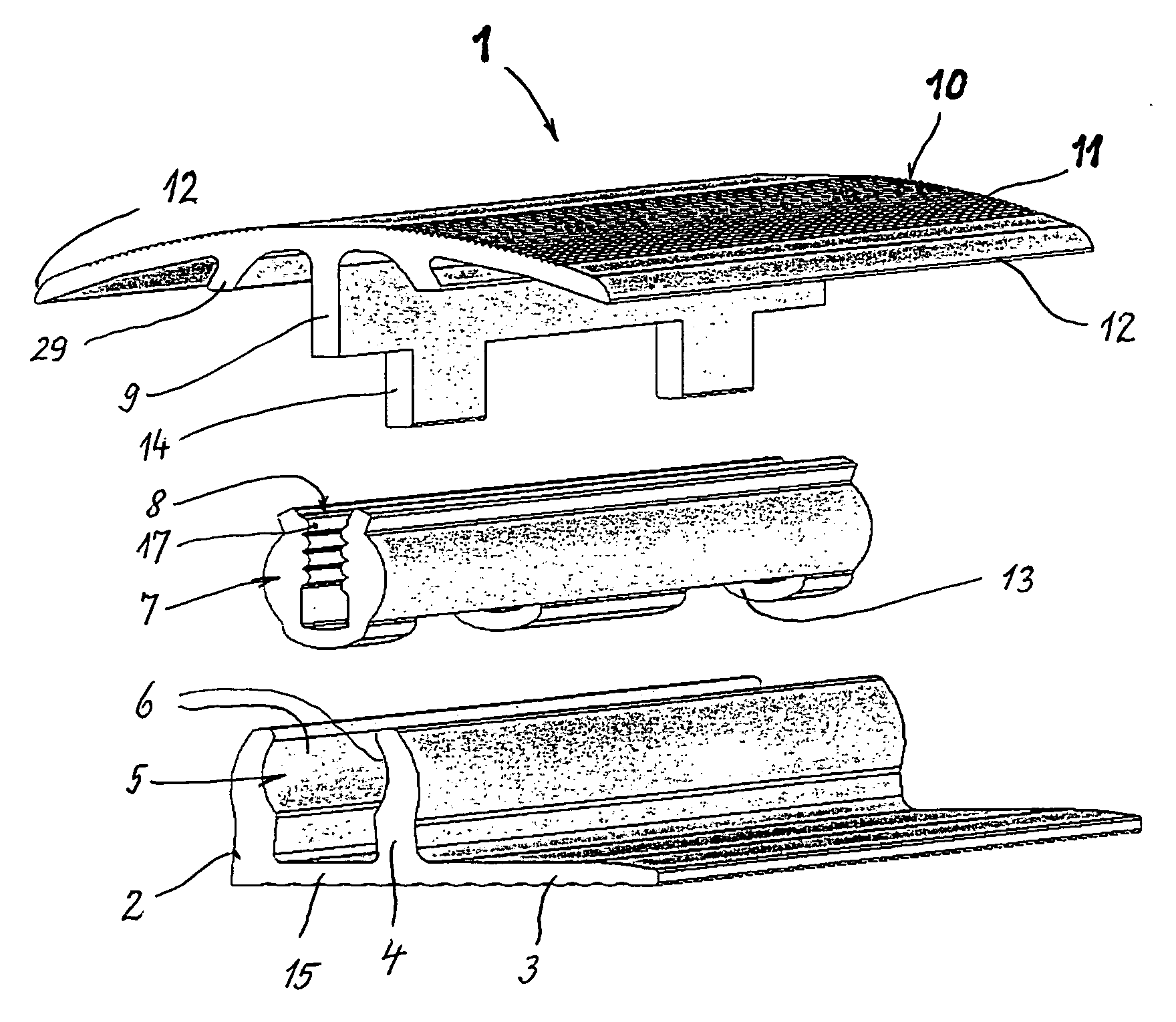
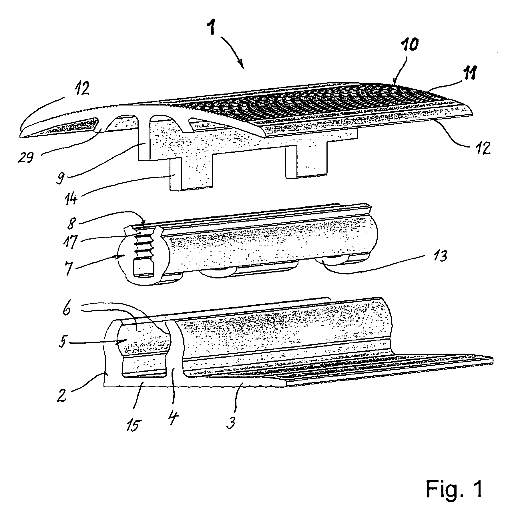
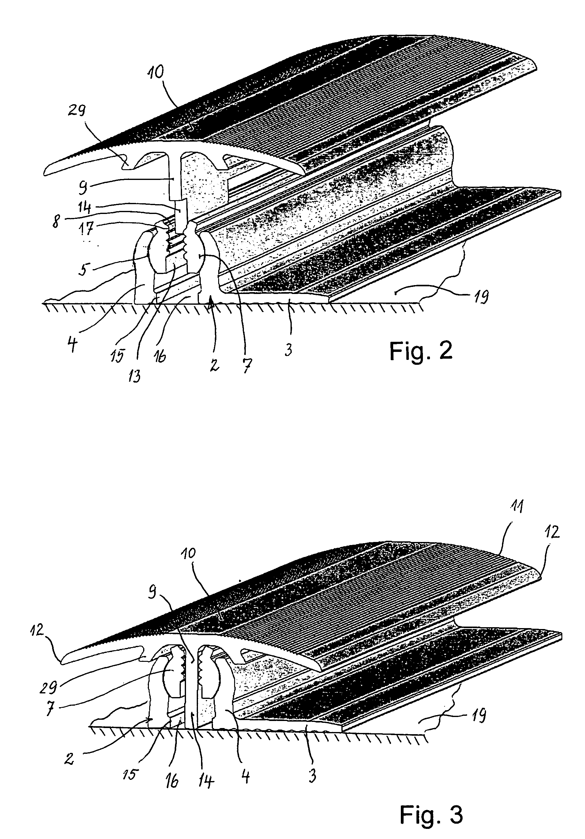
[0028]As can be seen in FIG. 1, floor strip 1 consists of a base profile 2, which has a lateral flange 3, with which it is fixed in place on the floor. Furthermore, two shanks 4 that are molded on and are directed upward proceed from base profile 2, which shanks are rounded on the inside and serve as articulation bearings 5. In articulation bearing 5, an articulation rail 7 is held by rounded inside surfaces 6 of shanks 4, so as to rotate. Articulation rail 7 is laterally adapted to the rounded regions of inside surface 6 of shanks 4, and has a groove 8 that is open toward the top, into which a crosspiece 9 of a cover profile 10 engages, which is molded onto the underside of cover profile 10. Cover profile 10 has two lateral wings 11, one of which could be angled away if cover profile 10 is used as an edge delimitation. With the two edges 12, cover profile 10 grasps the floor coverings, not shown, which form a join at the abutment point, which join is bridged by cover profile 10. Cr...
PUM
 Abstract
Description
Claims
Application Information