

Processing method for surface of workpiece using rotating cutting tool
a cutting tool and surface technology, applied in the direction of metal-working equipment, milling equipment, manufacturing tools, etc., can solve the problems of insufficient cutting quality of cut surfaces, and insufficient aesthetic appearance of knife marks as decorative patterns, so as to improve aesthetic appearance of decorative patterns and improve aesthetics. , the effect of fresh aesthetic appearan
- Summary
- Abstract
- Description
- Claims
- Application Information
AI Technical Summary
Benefits of technology
Problems solved by technology
Method used
Image

Examples
Embodiment Construction
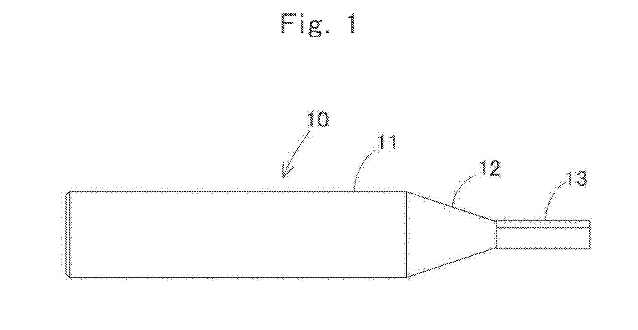
using the end mill according to Example 1.
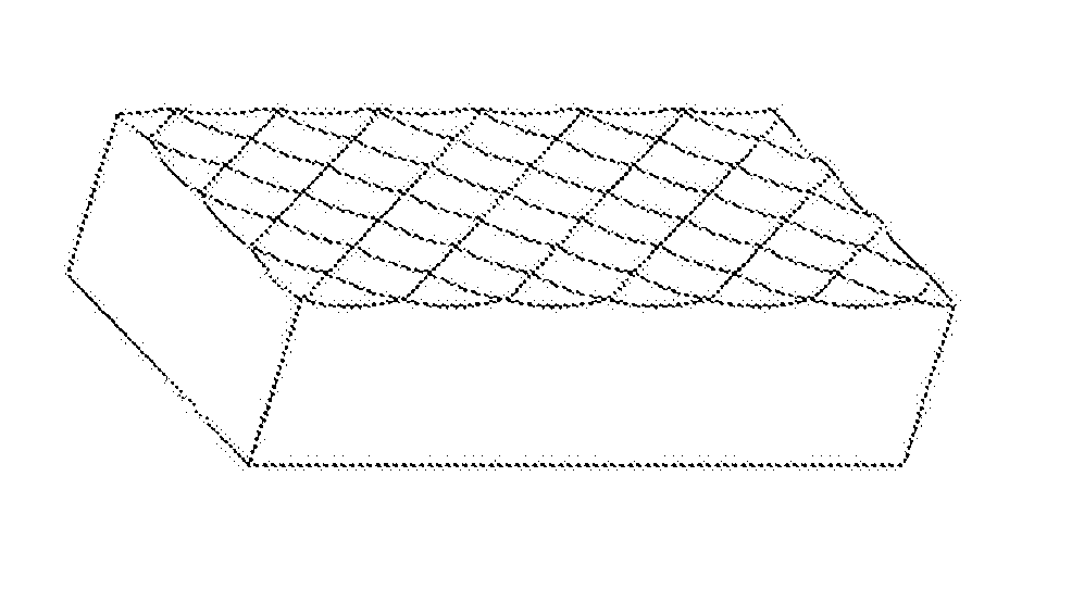
[0019]FIG. 3B is a perspective view showing Processing Example 1.
[0020]FIG. 4A is a plan view showing Processing Example 2 using the end mill according to Example 1.
[0021]FIG. 4B is a perspective view showing Processing Example 2.
[0022]FIG. 5A is a plan view showing Processing Example 3 using the end mill according to Example 1.
[0023]FIG. 5B is a perspective view showing Processing Example 3.
[0024]FIG. 6A is a plan view showing Processing Example 4 using the end mill according to Example 1.
[0025]FIG. 6B is a perspective view showing Processing Example 4.
[0026]FIG. 7A is a plan view showing Processing Example 5 using the end mill according to Example 1.
[0027]FIG. 7B is a perspective view showing Processing Example 5.
[0028]FIG. 8A is a plan view showing Processing Example 6 using the end mill according to Example 1.
[0029]FIG. 8B is a perspective view showing Processing Example 6.
[0030]FIG. 9A is a plan view showing Processing Example 7 using t...
PUM
 Abstract
Description
Claims
Application Information