Gas turbine engine curved diffuser with partial impingement cooling apparatus for transitions

Inactive Publication Date: 2007-08-02
SIEMENS ENERGY INC
View PDF27 Cites 24 Cited by
  • Summary
  • Abstract
  • Description
  • Claims
  • Application Information

AI Technical Summary

Problems solved by technology

However, radial diversion of a substantial portion of compressed air, without more, may present a problem when the airflow from the compressor has been used, or is desired to be used, to cool the transitions.

Method used


Image

  • Gas turbine engine curved diffuser with partial impingement cooling apparatus for transitions
  • Gas turbine engine curved diffuser with partial impingement cooling apparatus for transitions
  • Gas turbine engine curved diffuser with partial impingement cooling apparatus for transitions

Examples


Embodiment Construction

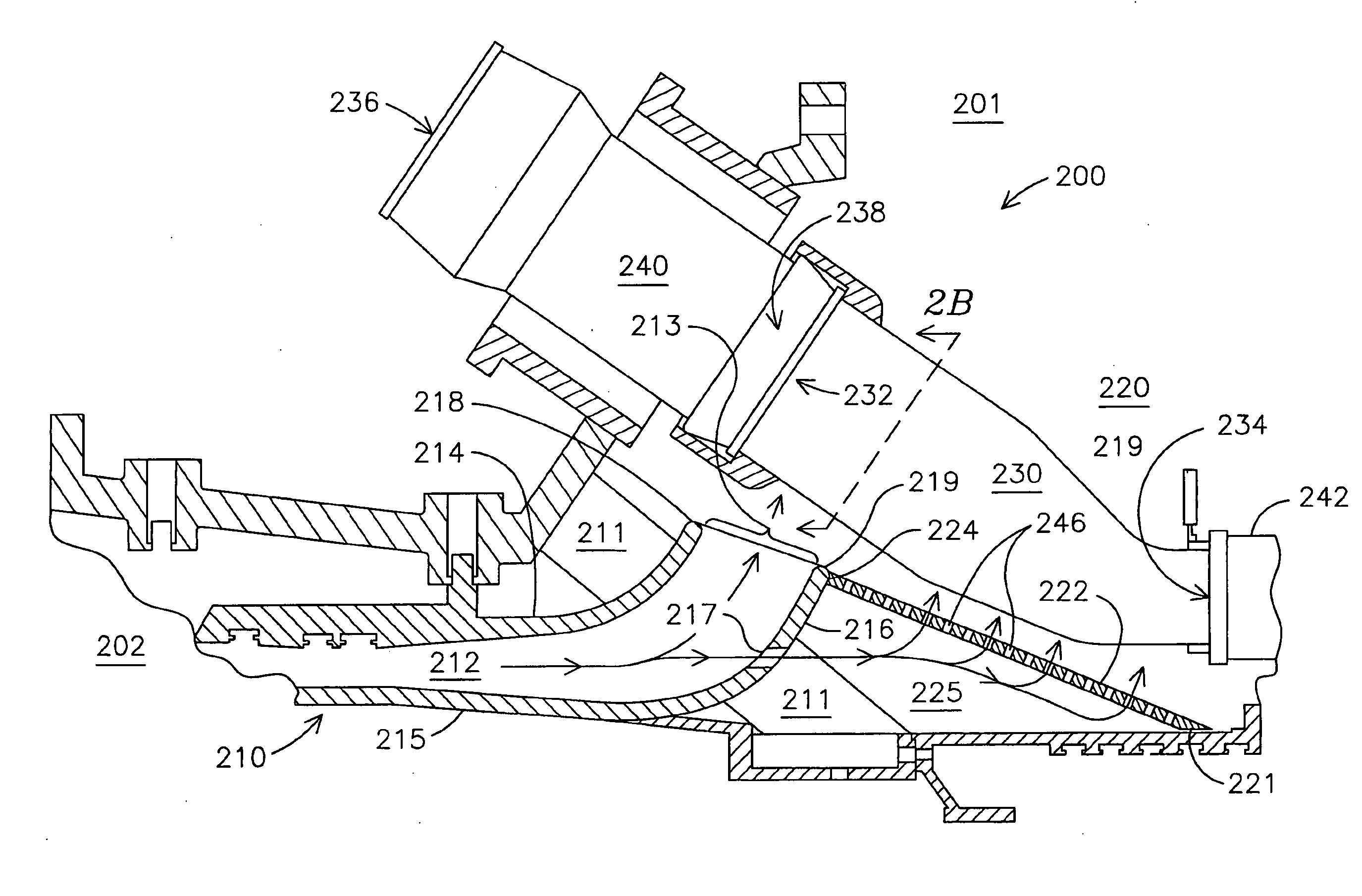
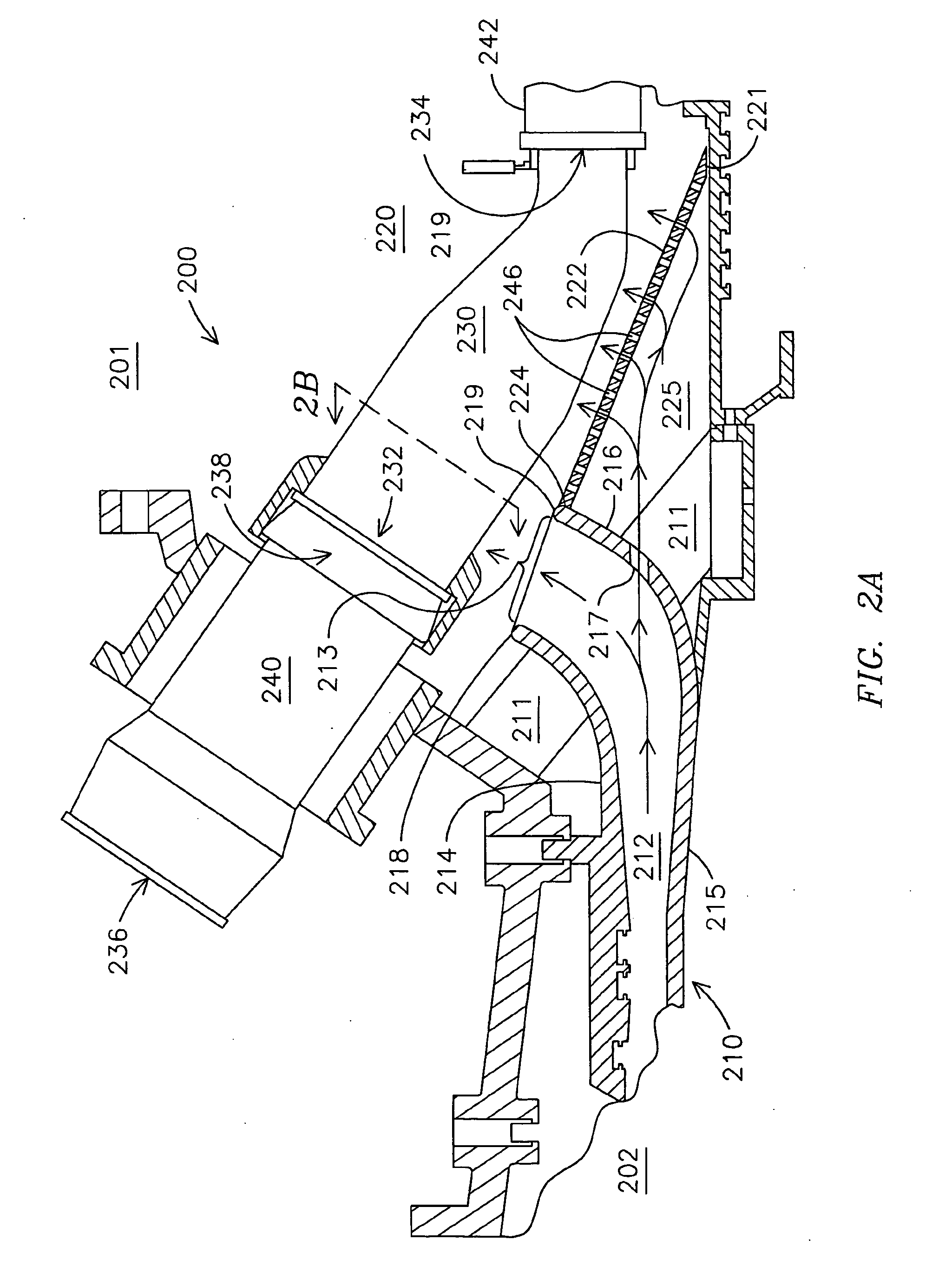
[0012] The present invention addresses the problems related to balancing the cooling of transitions of a gas turbine engine and efficient airflow through a plenum in which are positioned those transitions. These problems are solved with an assemblage of components adapted to provide a primary portion of air from the compressor efficiently directed to the intakes of the combustion chambers and a lesser, secondary portion of air directed to cool the transitions. One component comprises a diffuser comprising a arcuate surface, for example a curved outlet end, that directs the primary portion (taken to mean over 50 percent of the total flow) of the compressed air radially outwardly, and that also comprises a plurality of spaced-apart ports. These ports are adapted to provide the secondary portion of the compressed air to a second component, for cooling of the transitions.

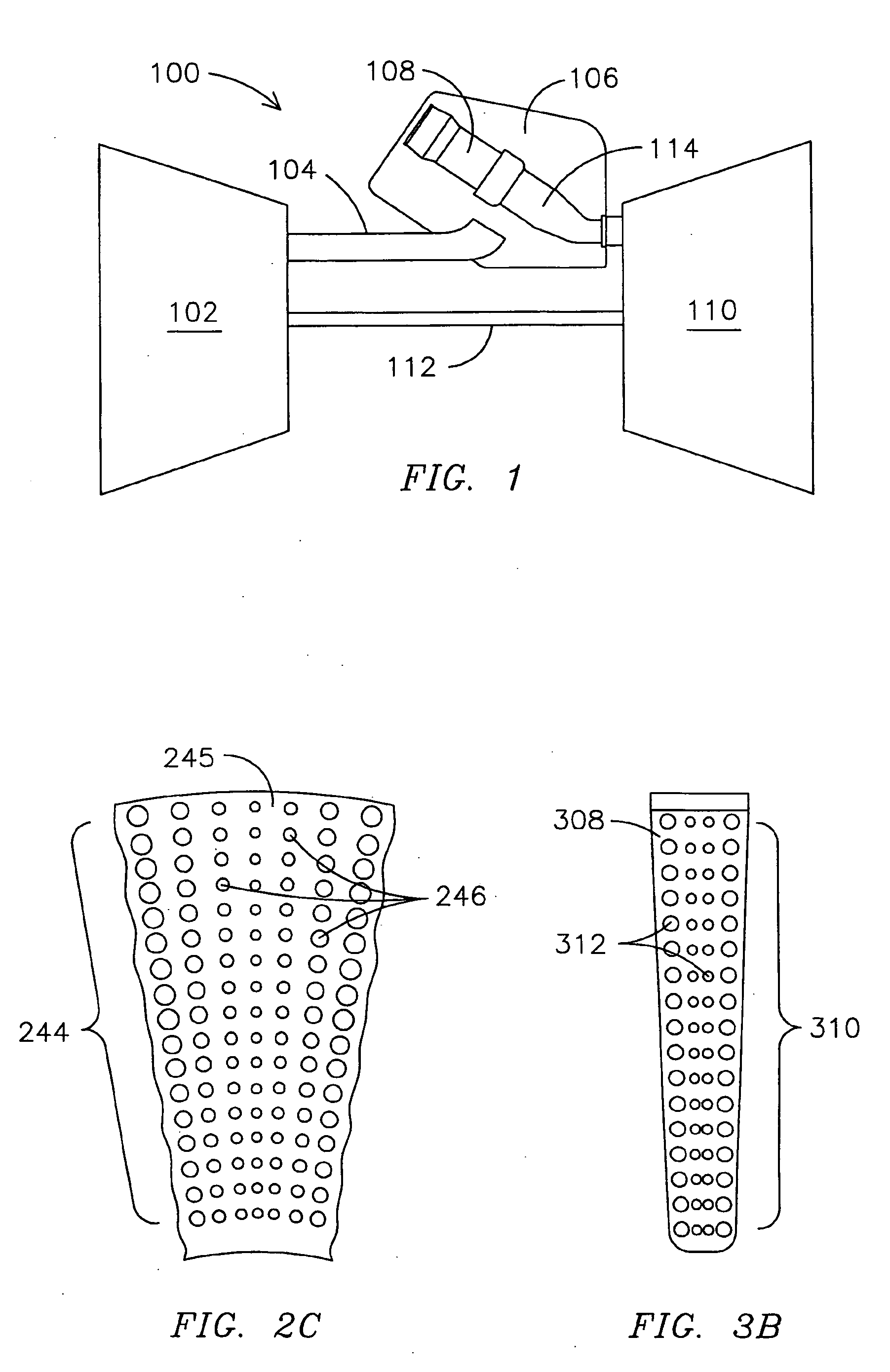
[0013] The second component comprises a pressure boundary element, which comprises an array of apertures disposed a ...


PUM


Abstract

A curved diffuser (210) in a gas turbine engine (201) directs a primary portion of air flow from a compressor (202) through a curved discharge opening (213) into a plenum (220). The curved diffuser (210) also comprises ports (217) through which a secondary portion of air passes into confined space (225) that is defined in part by a pressure boundary element that may be comprised of at least one plate (222) or at least one conduit (306). The at least one plate (222) and the at least one conduit (306) respectively comprise apertures (246, 312) through which pass the secondary portion of air to provide impingement-type cooling to transitions (230, 320). In various embodiments the velocity of the air between adjacent transitions (230, 320) may flow at relatively uniform velocity along the longitudinal distance of the respective transitions (230, 320).

Description

FIELD OF THE INVENTION [0001] The invention generally relates to a gas turbine engine with a compressor for supplying air. More particularly, it relates to an assemblage of components providing compressed air in a can-annular combustion chamber arrangement, where a portion of the air is directed for cooling transitions. BACKGROUND OF THE INVENTION [0002] In gas turbine engines air usually is compressed at an initial stage, then is heated in combustion chambers, and the hot gas so produced drives a turbine that does work, including rotating the compressor. [0003] To achieve a good overall efficiency in a gas turbine engine, one consideration is the reduction of losses of air pressure, such as due to friction and turbulence, between the air compressor and the intakes of the combustion chambers. In a common gas turbine engine design, compressed air flows from the air compressor, through a diffuser, into a plenum in which are positioned transitions and other components, and then from th...

Claims


Application Information

Patent Timeline
IPC IPC(8): F02C1/00
CPCF05D2260/201F01D9/023
Inventor BLAND, ROBERT J.
Owner SIEMENS ENERGY INC
Why Eureka
Try Eureka