Vacuum insulated switchgear

a switchgear and vacuum insulation technology, applied in the direction of switchgear arrangement, contact mechanism, air-break switch, etc., can solve the problem that the wiring pattern may sometimes suddenly change, and achieve the effect of high reliability, high reliability, and high reliability

Inactive Publication Date: 2007-08-02
HITACHI LTD
View PDF5 Cites 23 Cited by
  • Summary
  • Abstract
  • Description
  • Claims
  • Application Information

AI Technical Summary

Benefits of technology

[0011]The present invention has been accomplished based on the above background. One of objects of the present invention is to provide a vacuum insulated switchgear being downsized with high reliability, which can deal with the wiring patterns of the power cables in the installation site of the switchgears with flexibility, without changing the arrangement of the switchgears.
[0012]Another

Problems solved by technology

However, the wiring patterns ma

Method used


Image

  • Vacuum insulated switchgear
  • Vacuum insulated switchgear
  • Vacuum insulated switchgear

Examples


Embodiment Construction

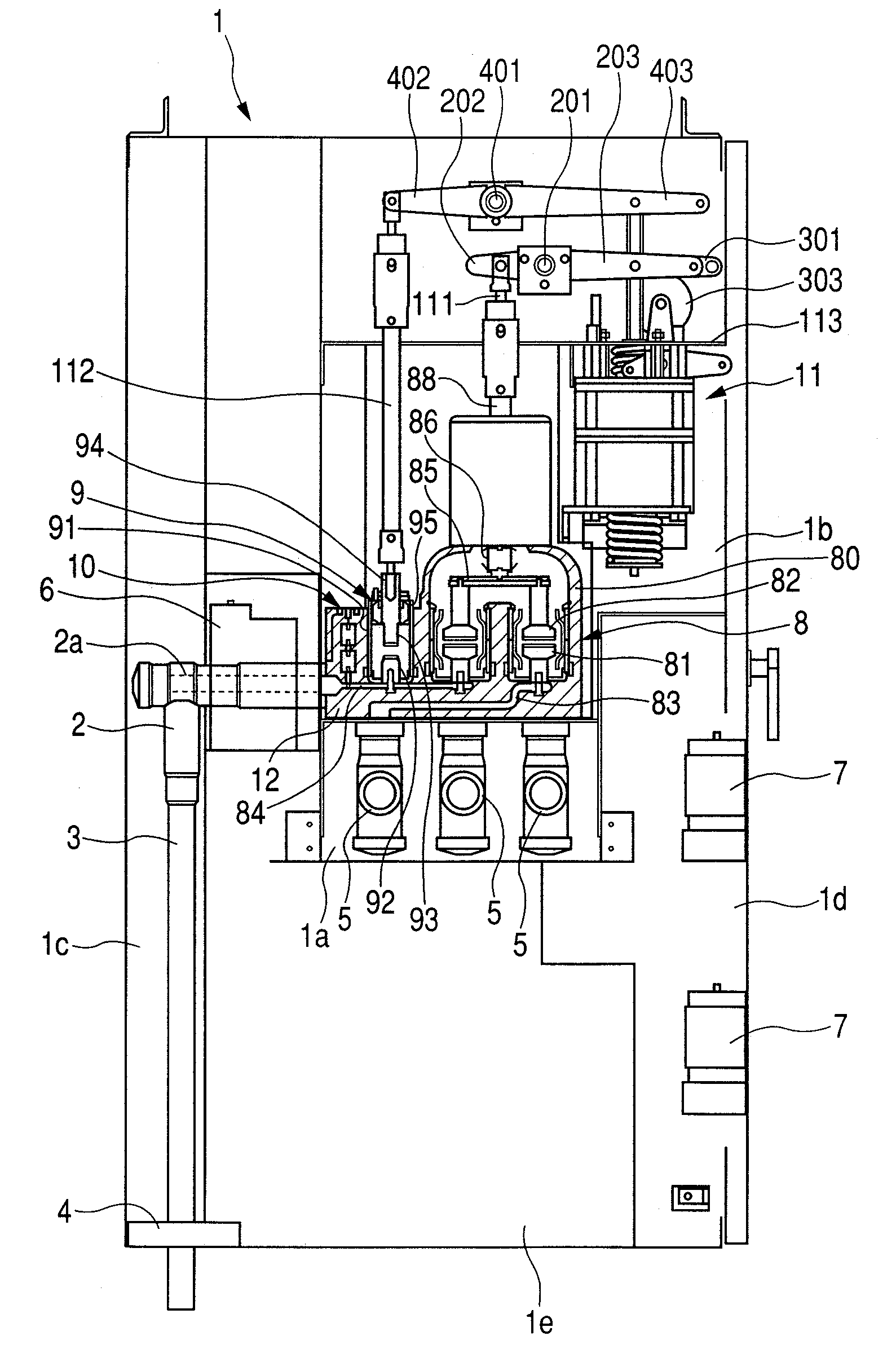
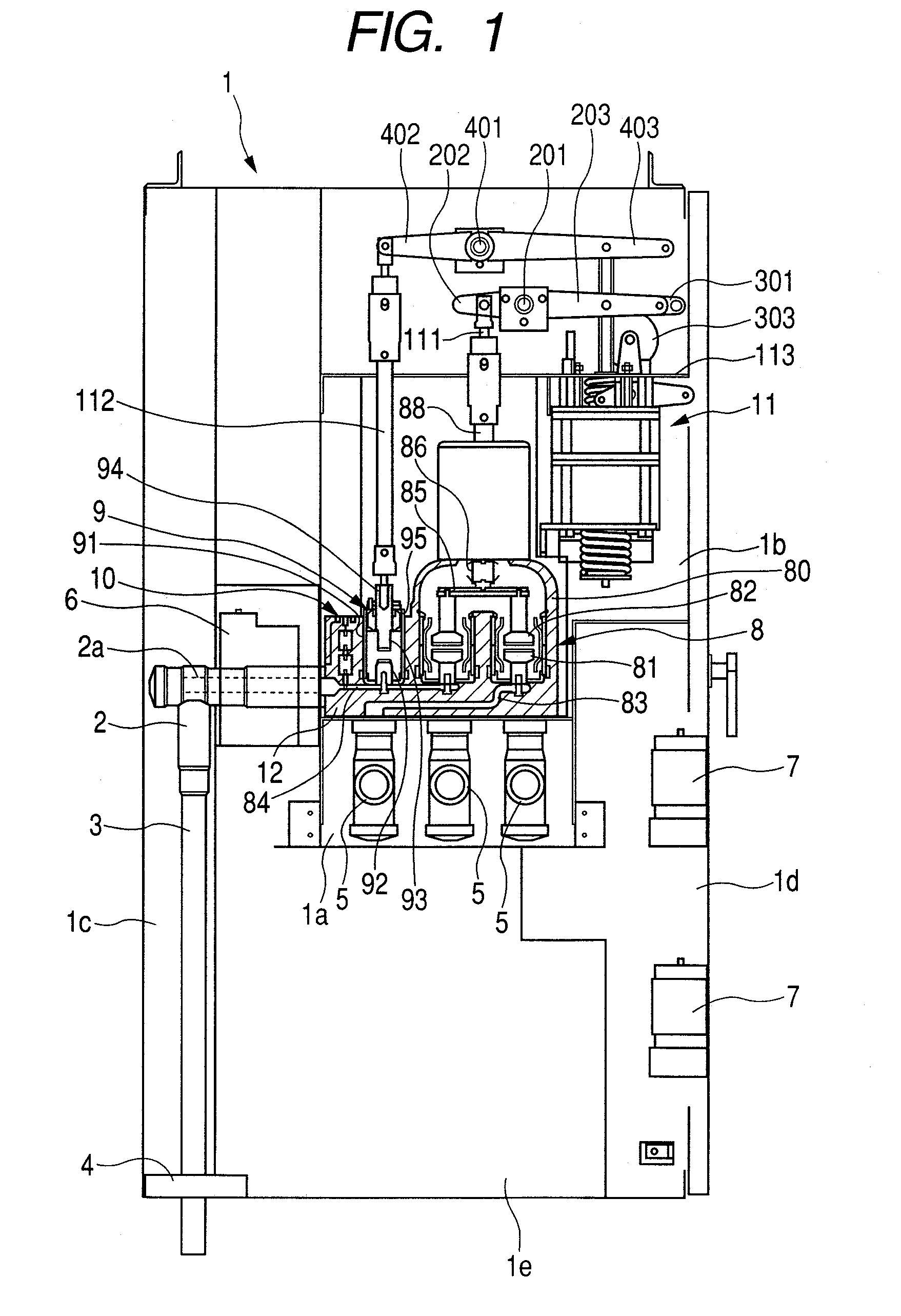
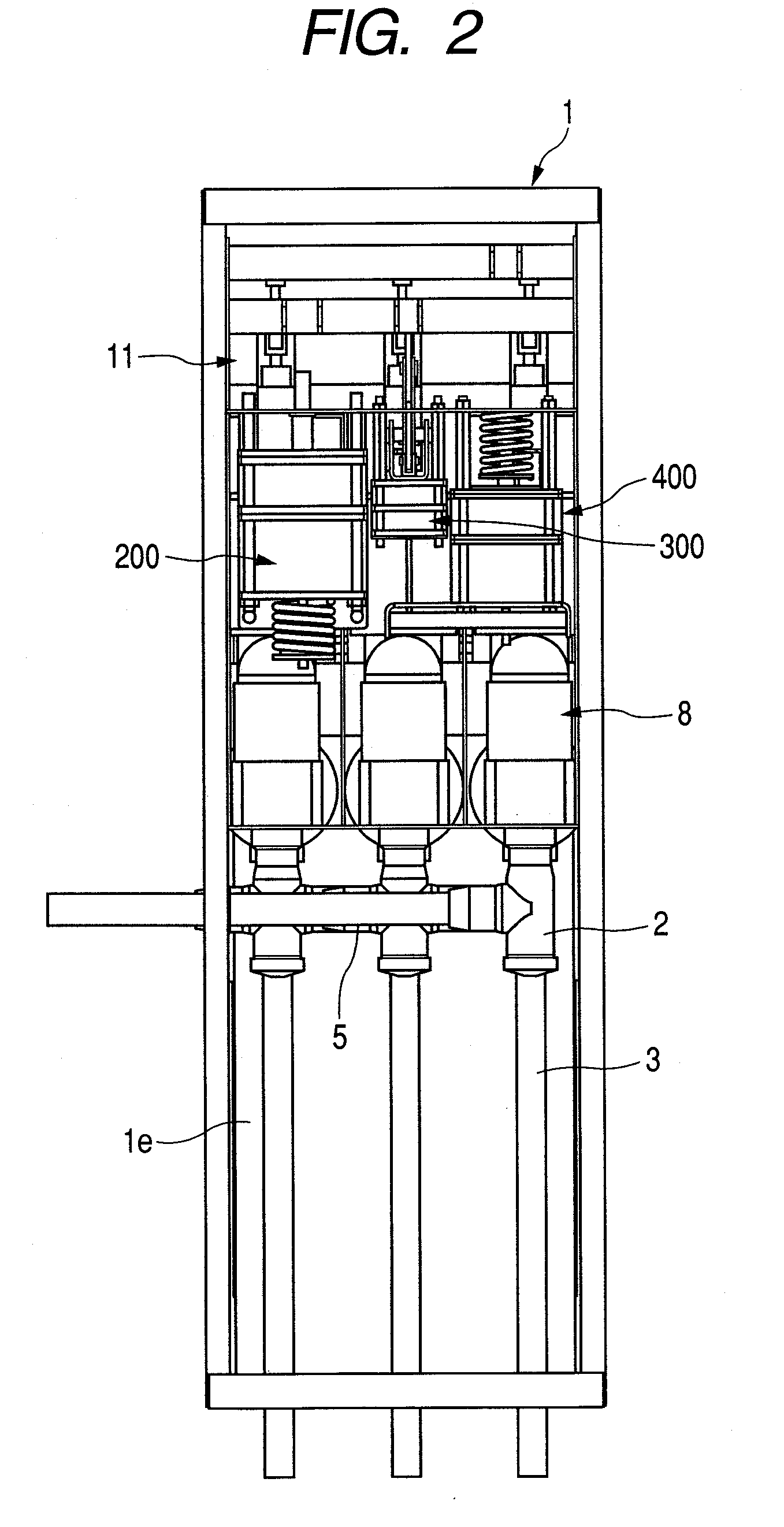
[0031]In order to achieve one or more of the objects, the vacuum insulated switchgear of the present invention comprises:

[0032]a metal case having a switch section, a bus-bar section and a cable section, each being portioned by an earthed metal plate;

[0033]a vacuum double break switch having breaking and disconnecting function, which switch is disposed in the switch section of the case;

[0034]an operator for opening and closing the vacuum double break switch;

[0035]a bus-bar disposed in the bus-bar section; and

[0036]a terminal introduced into the cable section, one end of which is connected to the switch and the other end is connected to the cable in the cable section, the cable being located at the rear end of the case to be connected to the cable in the cable section, and a transformer for measuring, connected to the terminal in the cable section by means of a fuse wherein the transformer is disposed below the bus-bar section of the case.

[0037]In order to achieve one or more of the ...


PUM


Abstract

A vacuum insulated switchgear comprising a case having a switch section, a bus-bar section and a cable section, each being partitioned by an earthed metal plate, a vacuum double break three point switch disposed in the switch section and having breaking and disconnecting function, an operator, a bus-bar disposed in the bus-bar section of the case, and a cable connection terminal connected to a cable in the cable section.

Description

CLAIM OF PRIORITY[0001]The present application claim priority from Japanese application serial No. 2006-22532, filed on Jan. 31, 2006, the content of which is hereby incorporated by reference into this application.FIELD OF THE INVENTION[0002]The present invention relates to a vacuum insulated switchgear, and more particularly to a vacuum insulated switchgear suitable for electric power distribution equipments.RELATED ART[0003]In the electric power distribution equipments, closed type switchboxes (so called switchgears) comprising a vacuum circuit breaker for breaking load current or fault current, an earthing switch and a disconnecting switch, both for protecting safety of workers, a sensor for detecting network voltage and current and a protection relay.[0004]In the switchgears of this type, wiring patterns of power cables for the switchgear in a site of installment has not sufficiently been considered. Thus, it has been desired that the arrangement of the switchgear is flexibly de...

Claims


Application Information

Patent Timeline
IPC IPC(8): H01H33/12
CPCH01H31/003H01H33/022H02B13/0354H01H2033/6623H01H2033/6668H01H33/66H02B13/02
Inventor TSUCHIYA, KENJIKIKUKAWA, SHUICHI
Owner HITACHI LTD
Why Eureka
Try Eureka