Rotary motion control device

Inactive Publication Date: 2007-08-02
MAP HLDG
View PDF22 Cites 35 Cited by
  • Summary
  • Abstract
  • Description
  • Claims
  • Application Information

AI Technical Summary

Benefits of technology

[0005] The invention is a rotary motion control device comprising a housing, a rotor, the rotor is adapted for connection to a rotary member to be braked, a magnetorheological material, the magnetorheological material is in contact with the rotor, a first set of magnets having alternating magnetic orientation and a second set of magnets having alternating magnetic orientation, the first and second sets of magnets

Problems solved by technology

The above brake is not satisfactory because the loading force is dependent upon the magnetic field generated in the gap extending between the magnet and the hysteresis material and adjustment of the gap to control the braking is difficult.
In addition, hysteresis materials are expensive and their inclusion within

Method used


Image

  • Rotary motion control device
  • Rotary motion control device
  • Rotary motion control device

Examples


Embodiment Construction

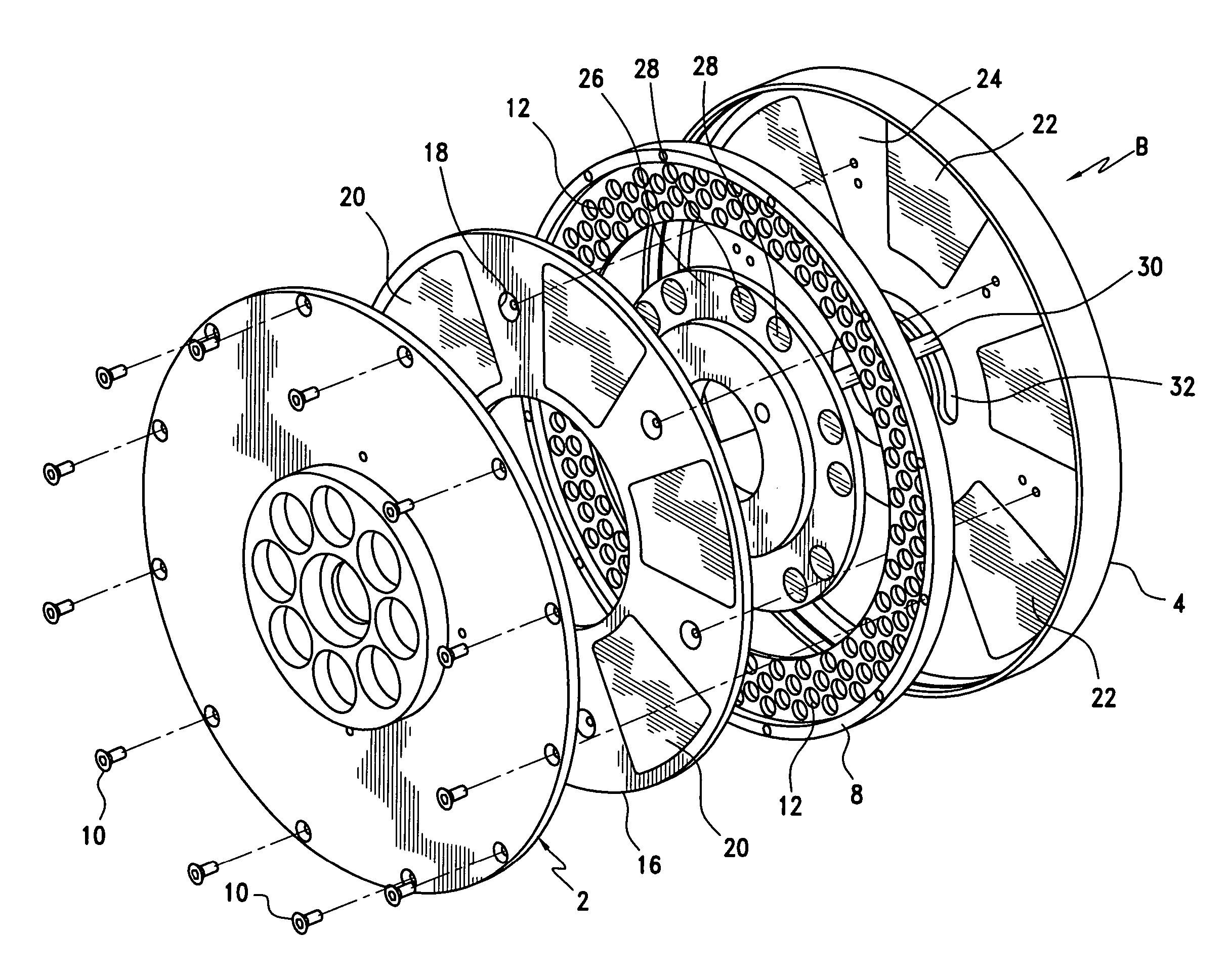
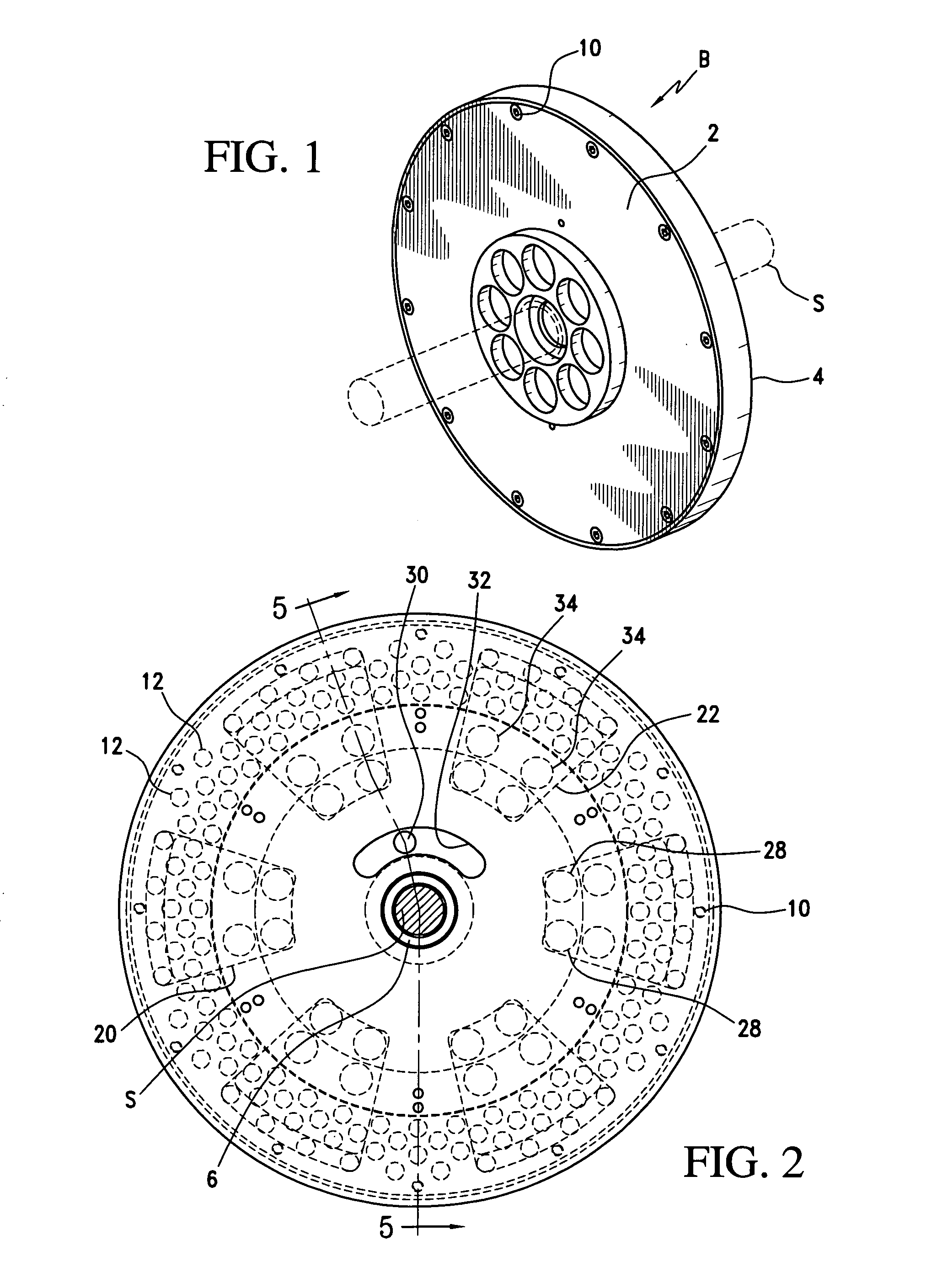
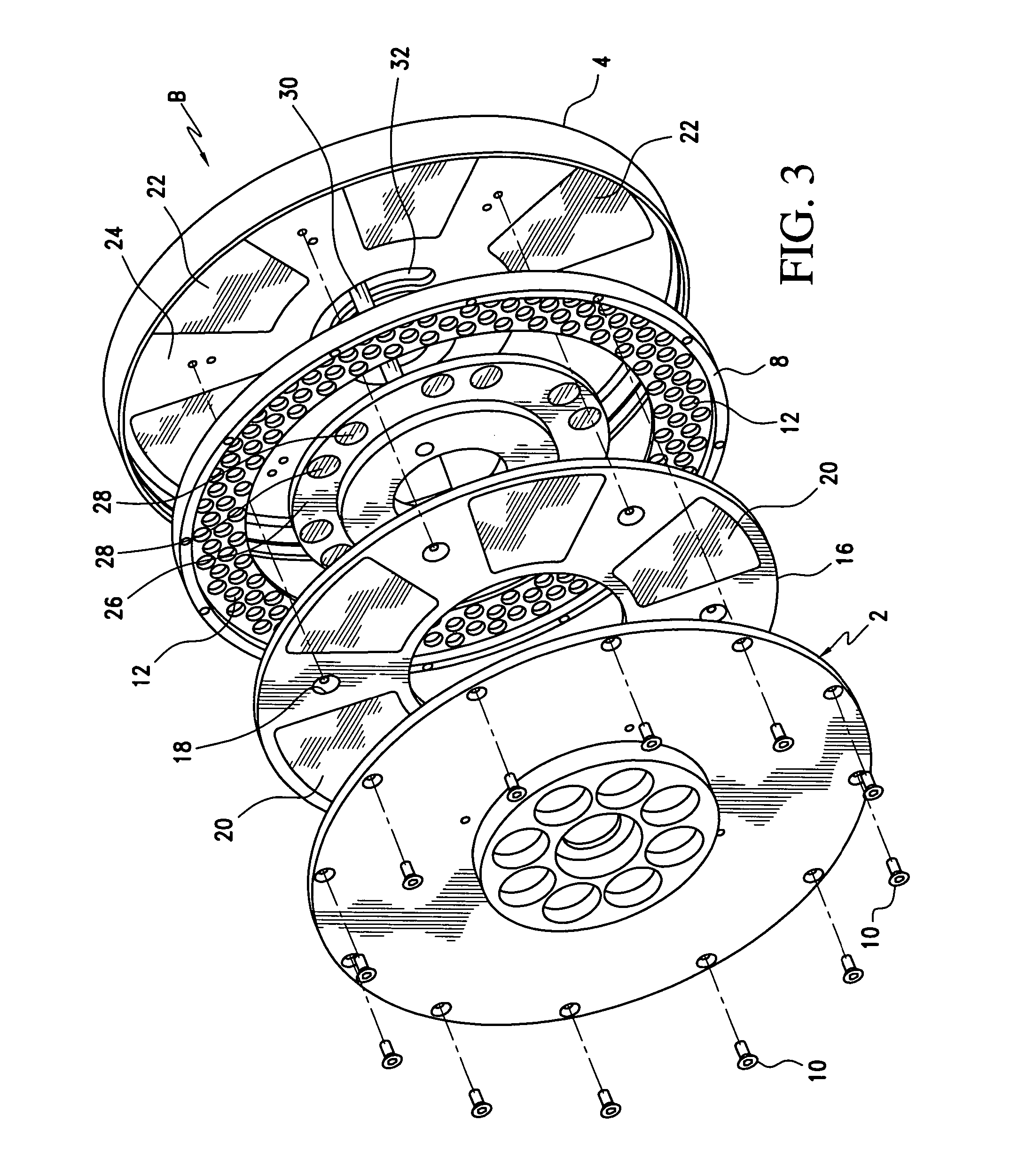
[0022] The brake or loading device according to a first embodiment of the invention is shown in FIGS. 1-6. The brake device B is shown provided with a housing or jacket formed from a rotating drive spool or plate 2 and a cup member 4 that is fixed relative to the drive plate 2. FIGS. 1 and 5 show the brake B supported on a shaft S via bearings 6.

[0023] Rotating drive spool 2 is fixed to a brake rotor 8 so that the rotor is movable with the drive spool 2. A series of connectors 10, shown in the drawings as rivets or screws, secure or otherwise connect the rotor 8 to the rotating drive spool 2. As is apparent, the drive spool 2 is adapted for rotation about its axis and is connected to a prime mover (not shown) to be braked. Rotor 8 is provided with a series of apertures or passageways 12 that extend through each side of the rotor.

[0024] A top plate 16, disposed between the drive spool 2 and rotor 8 is secured to cup 4 by screws or rivet-like connectors 18. As best shown in FIG. 3, ...


PUM


Abstract

This invention is a rotary motion control device comprising a housing, a rotor for connection to a rotary member to be braked, a magnetorheological material contacting the rotor, a first set of magnets having alternating magnetic orientation and a second set of magnets having alternating magnetic orientation, the first and second sets of magnets are adapted for selective alignment with respect to each other so that the magnetic orientation of one of the magnet sets may be repositioned relative to the other of the magnet sets to modulate the overall field strength of the magnets and change the viscosity of the magnetorheological material so that the shearing force on the rotor is increased or decreased. The invention further includes a fishing reel with a brake and a method for controlling the speed of a rotating member.

Description

FIELD OF THE INVENTION [0001] This invention relates to rotary motion control devices such as brakes, clutches and related couplings and in particular, a rotary motion control device having a magnetorheological material. BACKGROUND OF THE INVENTION [0002] Magnetic couplings in the form of brakes and clutches are known. In one prior art magnetic brake, the rotor is fitted with a hysteresis material and a yoke operatively associated with the rotor is provided with a permanent magnet so that relative rotation of the permanent magnet and the hysteresis material will result in a braking load. [0003] The above brake is not satisfactory because the loading force is dependent upon the magnetic field generated in the gap extending between the magnet and the hysteresis material and adjustment of the gap to control the braking is difficult. In addition, hysteresis materials are expensive and their inclusion within a brake will unduly increase the overall cost of the brake. [0004] It is also kn...

Claims


Application Information

Patent Timeline
IPC IPC(8): A01K89/02F16F9/53F16D67/00A01K89/015
CPCA01K89/01555A01K89/016F16F9/535F16D57/002A01K89/033
Inventor CAMPBELL, JOHN P.
Owner MAP HLDG
Why Eureka
Try Eureka