Dimple pivot post for a rotary co-located microactuator

a microactuator and pivot post technology, applied in the field of data storage systems, can solve the problems of insufficient single-stage actuation using the vcm, mechanical and electrical problems of the operation of magnetic disk drives, and the inability to achieve single-stage actuation, so as to improve the performance and track-follow control effectiveness, improve the performance and reliability of the read/write head, and eliminate the effect of hinge deformation

Inactive Publication Date: 2006-06-06
WESTERN DIGITAL TECH INC
View PDF12 Cites 220 Cited by
  • Summary
  • Abstract
  • Description
  • Claims
  • Application Information

AI Technical Summary

Benefits of technology

[0031]According to the present invention, the dimple post provides one more constraint (support) at the focal point of the loading force which offsets the two reaction forces exerted by aerodynamic lifting and gram load. Thus the hinge deformation is effectively eliminated.
[0032]The elimination of the hinge deformation affords the microactuator-based head-gimbal assembly a number of advantages, such as the

Problems solved by technology

A smaller track width poses several mechanical and electrical problems to the operation of magnetic disk drives.
One such problem lies in its actuation and control feature, which is critical to the operation of a magnetic disk drive.
As the track width reduces as a means to increase the track density and hence the storage capacity of magnetic disk drives, the foregoing single-stage actuation design encounters a significant degree of difficulty, mainly due to the excessive control error of the track-seek control using the VCM.
In particular, a single-stage actuation using the VCM is found to be inadequate because the resulting control error due to external disturbances, such as inertial shock loading or noise sometimes, could cause the read/write head to be positioned over tracks that are adjacent to the target track, thus possibly causing a magnetic field disturbance of the existing data thereon.
In a worst case scenario, the data disturbances can result in a total erasure of data in the adjacent tracks after several repeti

Method used


Image

  • Dimple pivot post for a rotary co-located microactuator
  • Dimple pivot post for a rotary co-located microactuator
  • Dimple pivot post for a rotary co-located microactuator

Examples


Embodiment Construction

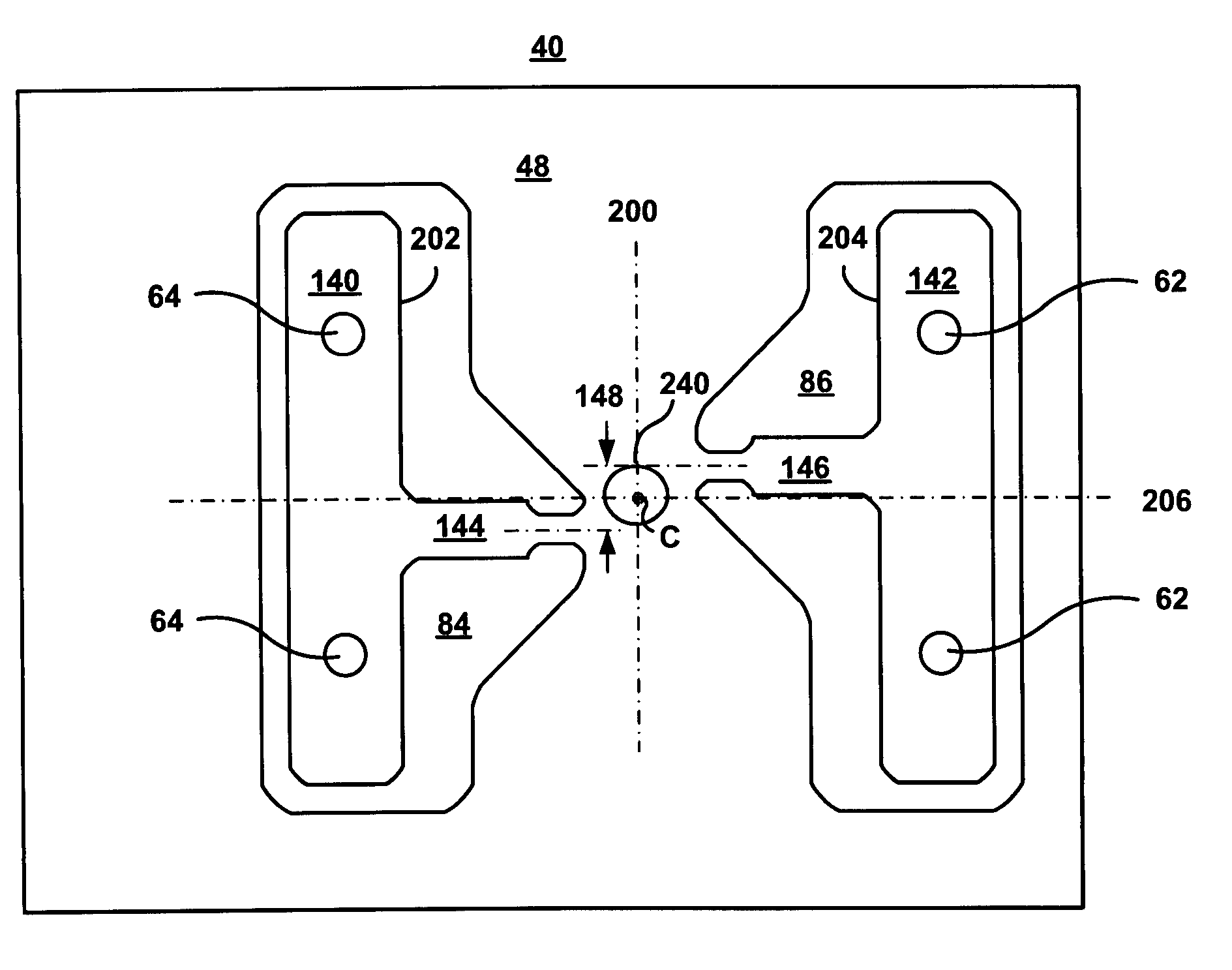
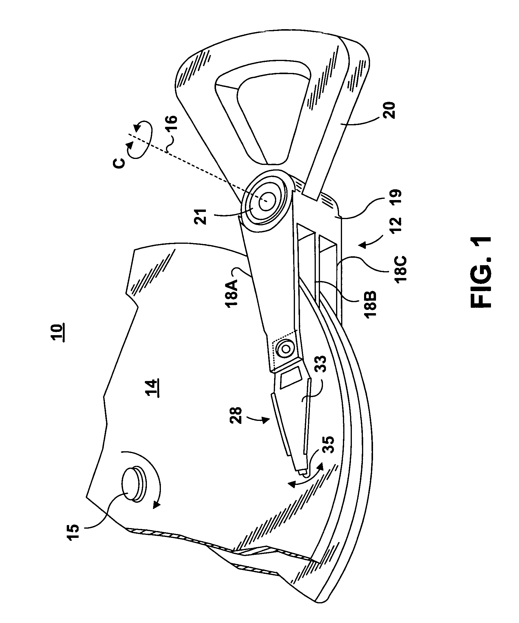
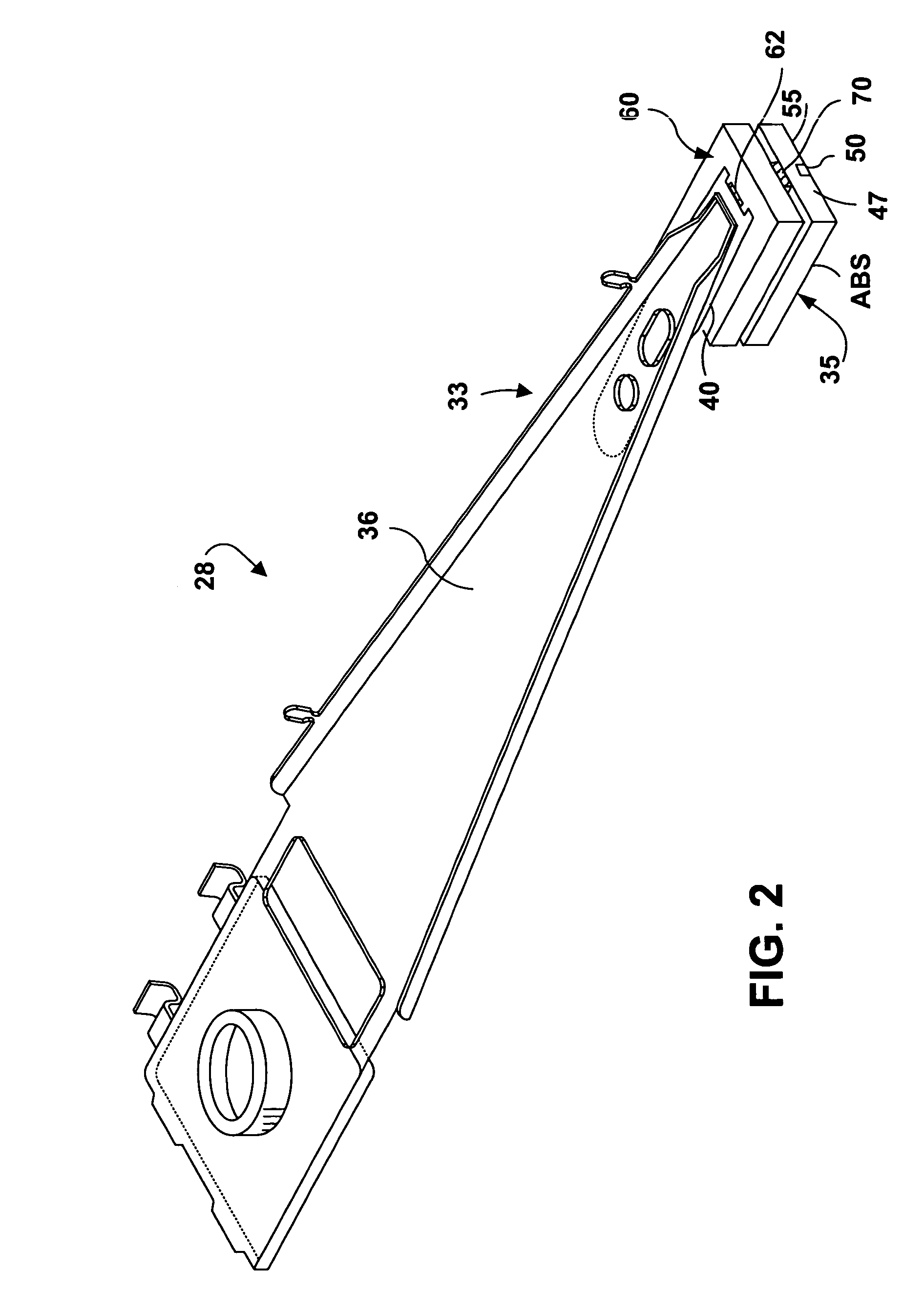
[0056]FIG. 1 illustrates a disk drive 10 comprised of a head stack assembly 12 and a stack of spaced apart smooth media magnetic data storage disks or smooth media 14 that are rotatable about a common shaft 15. The head stack assembly 12 is rotatable about an actuator axis 16 in the direction of the arrow C. The head stack assembly 12 includes a number of actuator arms, only three of which 18A, 18B, 18C are illustrated, which extend into spacings between the disks 14.

[0057]The head stack assembly 12 further includes an E-shaped block 19 and a magnetic rotor or voice coil motor (VCM) 20 attached to the block 19 in a position diametrically opposite to the actuator arms 18A, 18B, 18C. The VCM 20 cooperates with a stator (not shown) for rotating in an arc about the actuator axis 16. Energizing a coil of the rotor 20 with a direct current in one polarity or the reverse polarity causes the head stack assembly 12, including the actuator arms 18A, 18B, 18C, to rotate about the actuator axis...


PUM


Abstract

A rotary microactuator-based head-gimbal assembly design controls the unwanted deflection of a flexure in a data storage device and eliminates hinge deformation. The head-gimbal assembly maintains the co-planarity of the hinged islands in the microactuator under the applied load acting on the flexure and two associated hinged islands. The dimple post is placed at the dimple loading region of the flexure tongue and has the same height as adhesive dams on paddles secured to the hinged islands. The dimple post is formed by branching one of the existing conductive traces covered by a photoresist layer to the dimple loading region on flexure tongue. In an alternative embodiment, the dimple post is secured to the dimple loading region of the flexure tongue by means of adhesives with a variety of viscosity and elastic moduli.

Description

CROSS-REFERENCE TO RELATED APPLICATION[0001]The present application is related to patent application Ser. No. 10 / 016,027, titled “Microactuator With Offsetting Hinges And Method For High-Resolution Positioning Of Magnetic Read / Write Head,” filed Dec. 12, 2001, issued as U.S. Pat. No. 6,760,196, which is assigned to the same assignee as the present application, and which is incorporated herein by reference.FIELD OF THE INVENTION[0002]The present invention relates in general to data storage systems such as disk drives, and it particularly relates to a read / write head, such as a thin film head, a MR head, or a GMR head for use in such data storage systems. More specifically, the present invention provides a novel design of a rotary co-located microactuator, such as a piezoelectric microactuator, that is interposed between a flexure tongue and a slider to provide three-dimensional lateral (in-plane) and vertical (out-of-plane) micro-motion of the read / write head. The lateral motion can ...

Claims


Application Information

Patent Timeline
IPC IPC(8): G11B21/16
CPCG11B5/4826
Inventor NIU, YIMINFANSLAU, JR., EDMUND BRUNOLI, WEIJIN
Owner WESTERN DIGITAL TECH INC
Why Eureka
Try Eureka