
Method for manufacturing rigidity-flexibility combined printing circuit board

A technology for printed circuit boards and manufacturing methods, applied in the directions of printed circuit manufacturing, printed circuits, electrical components, etc., can solve problems such as unreasonable process steps, affecting assembly, complexity, etc., to avoid damage to the cover film, improve production efficiency, Reasonable effect of process steps

Active Publication Date: 2013-03-13
CHENGDU AEROSPACE COMM EQUIP CO LTD
View PDF2 Cites 17 Cited by
  • Summary
  • Abstract
  • Description
  • Claims
  • Application Information

AI Technical Summary

Problems solved by technology

[0004] At present, due to the cumbersome and complicated manufacturing process of rigid-flex printed circuit boards, it is difficult to improve the production quality and eradicate various defects. It will cause expansion and contraction, which will affect the relative position of the device hole, thereby affecting the alignment of the subsequent process (primary imaging, secondary imaging), and more seriously, the downstream assembly; when the process steps are unreasonable, it is easy to cause the milling window. Damage to the cover film and low production efficiency; the tape protecting the window of the rigid board is easy to fall off, causing the acid-base solution to corrode the flexible area; the parameter setting of the laminator is unreasonable in the steps of laminating the cover film of the flexible board and the lamination of the rigid-flex board , resulting in unsatisfactory product lamination quality

Method used


Image

  • Method for manufacturing rigidity-flexibility combined printing circuit board
  • Method for manufacturing rigidity-flexibility combined printing circuit board
  • Method for manufacturing rigidity-flexibility combined printing circuit board

Examples


Embodiment 1

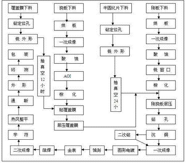
[0020] Such as figure 1 As shown, a rigid-flex printed circuit board manufacturing method, including cover film preparation, flexible board preparation, prepreg preparation, rigid board preparation and rigid-flex board production.

[0021] Cover film preparation consists of the following steps:

[0022] Covering film cutting → drilling positioning holes → milling shape → vacuuming for 24 hours;

[0023] Flex board preparation includes the following steps:

[0024] Flexible plate blanking→baking plate→one-time imaging→acid etching→AOI→browning→attaching cover film→laminating cover film;

[0025] The cover film used in the step of pasting the cover film is the cover film prepared from the above cover film.

[0026] Prepreg preparation involves the following steps:

[0027] Prepreg blanking→drilling positioning holes→milling the shape→vacuumizing for 24 hours;

[0028] Rigid board preparation consists of the following steps:

[0029] Rigid plate blanking→baking plate→one im...

Embodiment 2

[0056] A method for manufacturing a rigid-flexible printed circuit board. The step of milling a window is to mill a groove on the surface of the rigid-flexible board with a depth of one-third of the plate thickness. After the on-off test step, the groove is milled through to form a window, so as to remove the flexible board. area rigid plate purpose, the continuity test procedure is figure 1 On-off in. This method requires high glue flow control and high milling precision. If the precision control is not good, the flex plate will be milled. However, the subsequent processing of this window opening method does not require window protection. This method is only applicable to products where the distance between the edge of the rigid board window and the pad is less than 2mm. The specific process is as follows:

[0057] Rigid board imaging→acid etching→primary slotting (1 / 3 depth of board thickness)→rigid-flexible board lamination→drilling→immersion copper plating→……→continuity tes...


PUM


Abstract

The invention discloses a method for manufacturing a rigidity-flexibility combined printing circuit board. The method comprises the following steps of: laminating a rigidity-flexibility board, milling a window, electrically plating electroless plating copper, imaging, silk-screening and solder-resisting, flattening with hot air, carrying out on-off test, removing drilling dirt in holes, and laminating a coverage film by using a flexible board, wherein the steps of covering the coverage film by using the flexible layer and laminating the rigidity-flexibility board on an optical drawing machine for compensating an expansion amount; the total expansion amount is compensated to a primary imaging working substrate; and the transformation generated in a manufacturing process can be eliminated by using the compensation of the working substrate, so that the good alignment product can be obtained. The process steps are reasonable, so that the coverage film can be prevented from being damaged in a process of milling the window, and the production efficiency can be improved; an adhesive tape provided by the invention can be used for protecting the rigid board window, and the adhesive tape not only can resist erosion of an acid and alkali solution but also has high-temperature resistance and strong adaptability; and the parameter arrangement and the step of a laminating machine can be optimized by the steps of laminating the coverage film by the flexible board and laminating the rigidity-flexibility board, thus ideal product laminating quality is achieved.

Description

technical field [0001] The invention relates to a method for manufacturing a rigid-flexible printed circuit board. Background technique [0002] With the development of electronic equipment, especially the development trend of electronic equipment such as mobile phones and digital cameras towards lightness, thinness, shortness and smallness, the only way to reduce the volume of finished products is to reduce parts or combine parts into modules. Realization, the characteristics of the rigid-flex board just meet these requirements. It can effectively use the installation space, realize three-dimensional assembly, reduce installation costs, and can replace plug-ins, and can ensure reliability in shock, humidity and other environments. Rigid-flex boards not only have the support of rigid printed boards, but also Due to the characteristics of flexible boards, due to its remarkable advantages, it has more and more application prospects, especially in aerospace and military fields...

Claims


Application Information

Patent Timeline
IPC IPC(8): H05K3/00
Inventor 马忠义杨朝志李丹杨德智刘厚文
Owner CHENGDU AEROSPACE COMM EQUIP CO LTD
Learn More