Spring connector

a technology of spring connector and connector, which is applied in the direction of coupling contact member, coupling device connection, printed circuit, etc., can solve the problems of large overall height of the spring connector, deformation of the housing 60/b>, and warping upwards

Inactive Publication Date: 2008-10-14
YOKOWO CO LTD
View PDF7 Cites 18 Cited by
  • Summary
  • Abstract
  • Description
  • Claims
  • Application Information

AI Technical Summary

Benefits of technology

[0014]It is therefore an object of the invention to provide a spring connector in which a thickness of an upper portion of a housing can be made thinner through provision of a normal holding structure that eliminating deformation of the resin housing, thereby achieving a low-profile design of the whole of the spring connector.

Problems solved by technology

However, the following problems may occur in the spring connector 100 of the related art.
Namely, when the stresses are applied to an upper portion of the housing 60, which also has the slits 63 in its lower portion, this results in a problem in that the lower portions of the slits 63 are widened, so that the whole of the housing 60 is warped upwardly.
Accordingly, there is also a fear that the housing 60 may be further deformed by the influence of heat during the heating.
To avoid this deformation, it is necessary to thicken the upper portion of the housing 60 (the portion disposed above the hole portions 61), and therefore this leads to a drawback in that the overall height of the spring connector becomes large.

Method used


Image

  • Spring connector
  • Spring connector
  • Spring connector

Examples


Embodiment Construction

[0031]Embodiments of the present invention will now be described with reference to FIGS. 1 to 9. The same construction as that of the above-mentioned related art will be designated by identical reference numerals, and explanation thereof will be omitted.

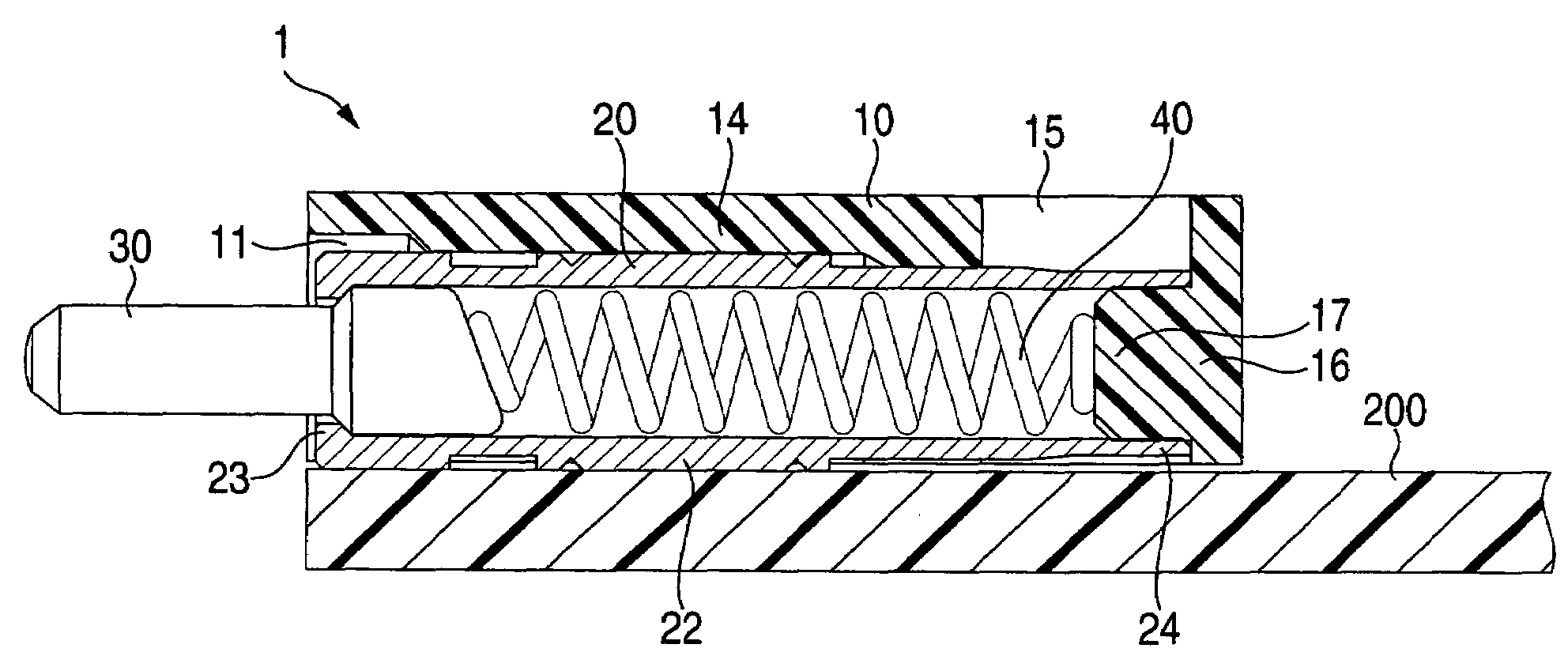
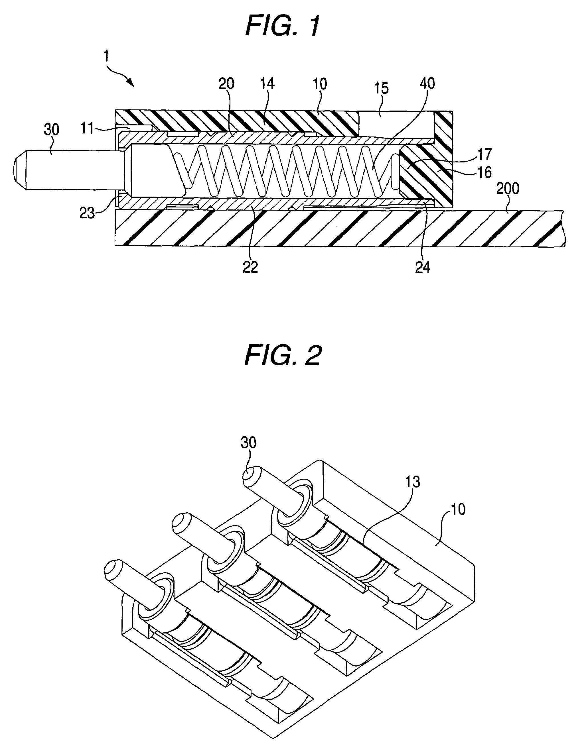
[0032]FIG. 1 is a schematic view of a first embodiment of a spring connector of the present invention, and FIG. 2 is an external perspective view. In the spring connector 1 in the drawings, 10 denotes a resin-made insulative housing, 20 denotes a tube made of an electrically-conductive material, 30 denotes a pin, and 40 denotes a spring.

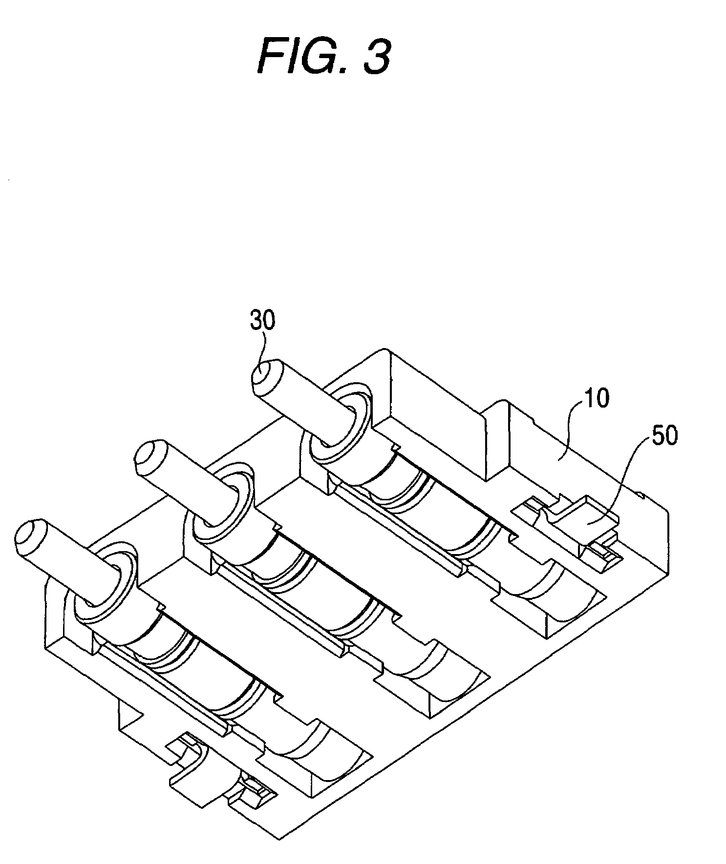
[0033]Hole portions 11 into which the tubes 20 can be inserted, respectively, are provided in the housing 10, and slits 13 communicating respectively with the hole portions 11 are provided in a lower portion of the housing 10, and the tube 20 inserted in the hole portion 11 is held within the housing 10 in such a condition that a mounting portion 22 formed on a generally longitudinally-central portion...


PUM


Abstract

A spring connector includes: an electrically-conductive pin; an electrically-conductive tube, having the pin slidably received therein, the tube holding the pin in such a condition that at least part of the pin projects from one end of the tube in a first direction, and the other end of the tube being open; and a housing, including a hole portion which can receive the tube, and a slit exposing at least part of an outer peripheral surface of the tube to an exterior, the housing having a first wall portion opposed to the other end of the tube and formed with a projecting portion projecting in the first direction and fitting to the other end of the tube. The at least part of the outer peripheral surface of the tube which is exposed from the slit is electrically connectable to a board.

Description

BACKGROUND OF THE INVENTION[0001]This invention relates to a connector used in an electronic equipment such as a cellular phone, and particularly to a right angle-type spring connector mounted horizontally on a board.[0002]A cellular phone contains a battery as a main power source, and this battery and an equipment body are electrically connected together via a spring connector mounted on a printed wiring board of the equipment body.[0003]With the achievement of a low profile design of cellular phones in recent years, there has been an increasing demand for a low-profile design of the spring connector.[0004]A spring connector 100 of the related art is shown in FIGS. 10 and 11.[0005]The spring connector 100 of the related art is surface mounted on a board 200, and in FIG. 10, 60 denotes a resin-made insulative housing, 70 denotes a tube made of an electrically-conductive material, 30 denotes a pin, and 40 denotes a spring. Within the housing 60, the plurality of pins 30 having electr...

Claims


Application Information

Patent Timeline
Patent Type & Authority Patents(United States)
IPC IPC(8): H01R12/00
CPCH01R13/2421H01R12/714
Inventor SUGIURA, KENTA
Owner YOKOWO CO LTD
Why Eureka
Try Eureka