Frame structure for stereoscopic imaging

Inactive Publication Date: 2011-06-28
CREAT3
View PDF12 Cites 17 Cited by
  • Summary
  • Abstract
  • Description
  • Claims
  • Application Information

AI Technical Summary

Benefits of technology

[0029]In yet a further embodiment, the first and second rigid binding members are slidably connected to the elongated members to enable selective movement of the camera mounting member and of the corresponding camera mounted thereto towards and away from the casing. This configuration is of great advantage to enable the corresponding camera to be set to a desired distance from the beam splitting device.
[0030]In anothe

Problems solved by technology

Unfortunately, most of the frame structures of the prior art do not allow the cameras to be properly supported.
This load may subject the post members to out-of-plane bending relative to the support plane and thereby cause deformations in the post members, especially when the frame structure is moved, for instance to record images of a moving subject.
Since precise positioning of the cameras is required to obtain a desired three-dimensional image, such deformations may require a user to periodically stop recording of the subject to readjust pos

Method used


Image

  • Frame structure for stereoscopic imaging
  • Frame structure for stereoscopic imaging
  • Frame structure for stereoscopic imaging

Examples


Embodiment Construction

[0043]In the following description of the embodiments, references to the accompanying drawings are by way of illustration of an example by which the invention may be practiced. It will be understood that other embodiments may be made without departing from the scope of the invention disclosed.

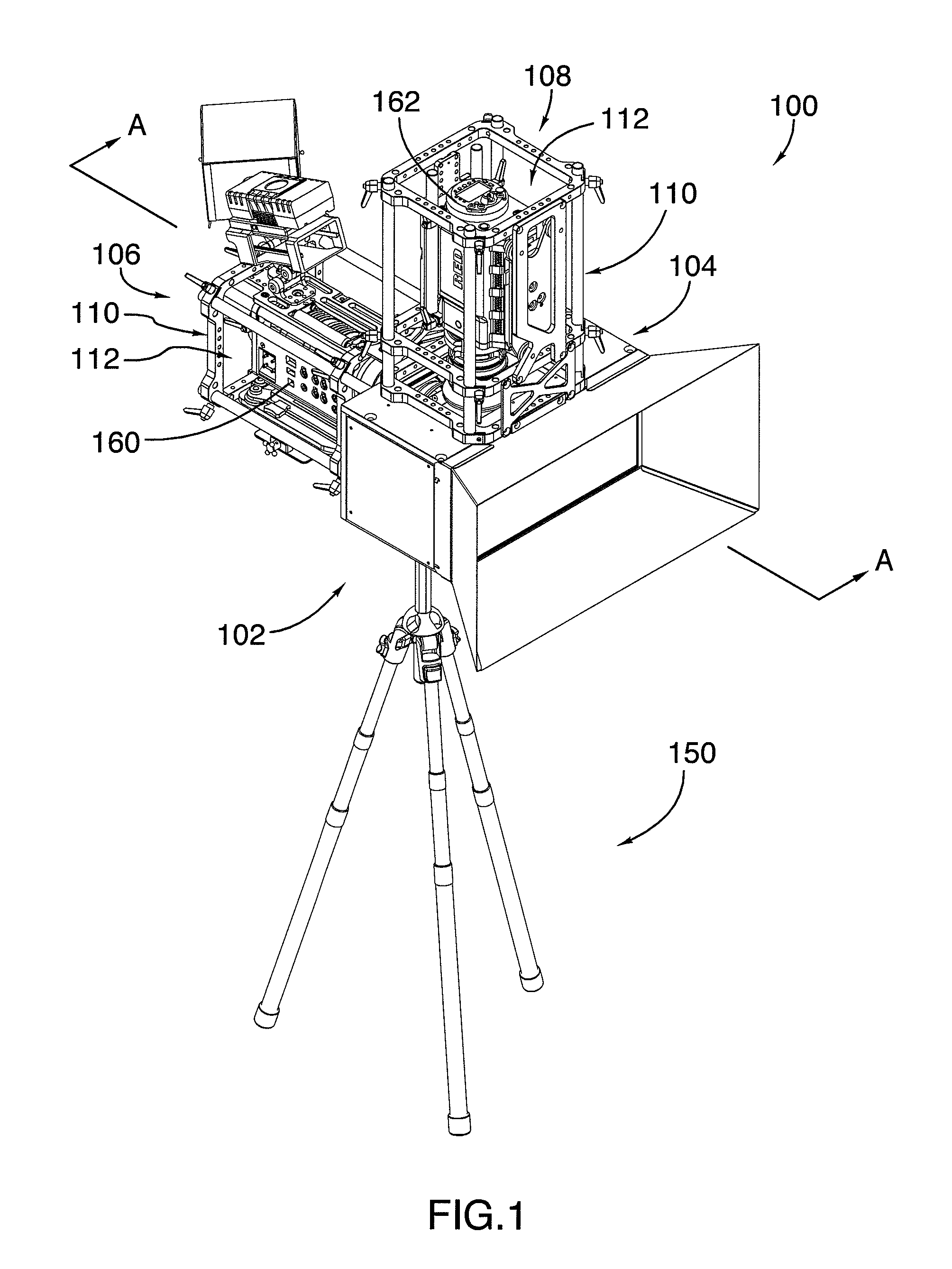
[0044]Referring to FIGS. 1 and 2, there is provided a stereoscopic camera rig 100 for stereoscopic imaging, in accordance with one embodiment.

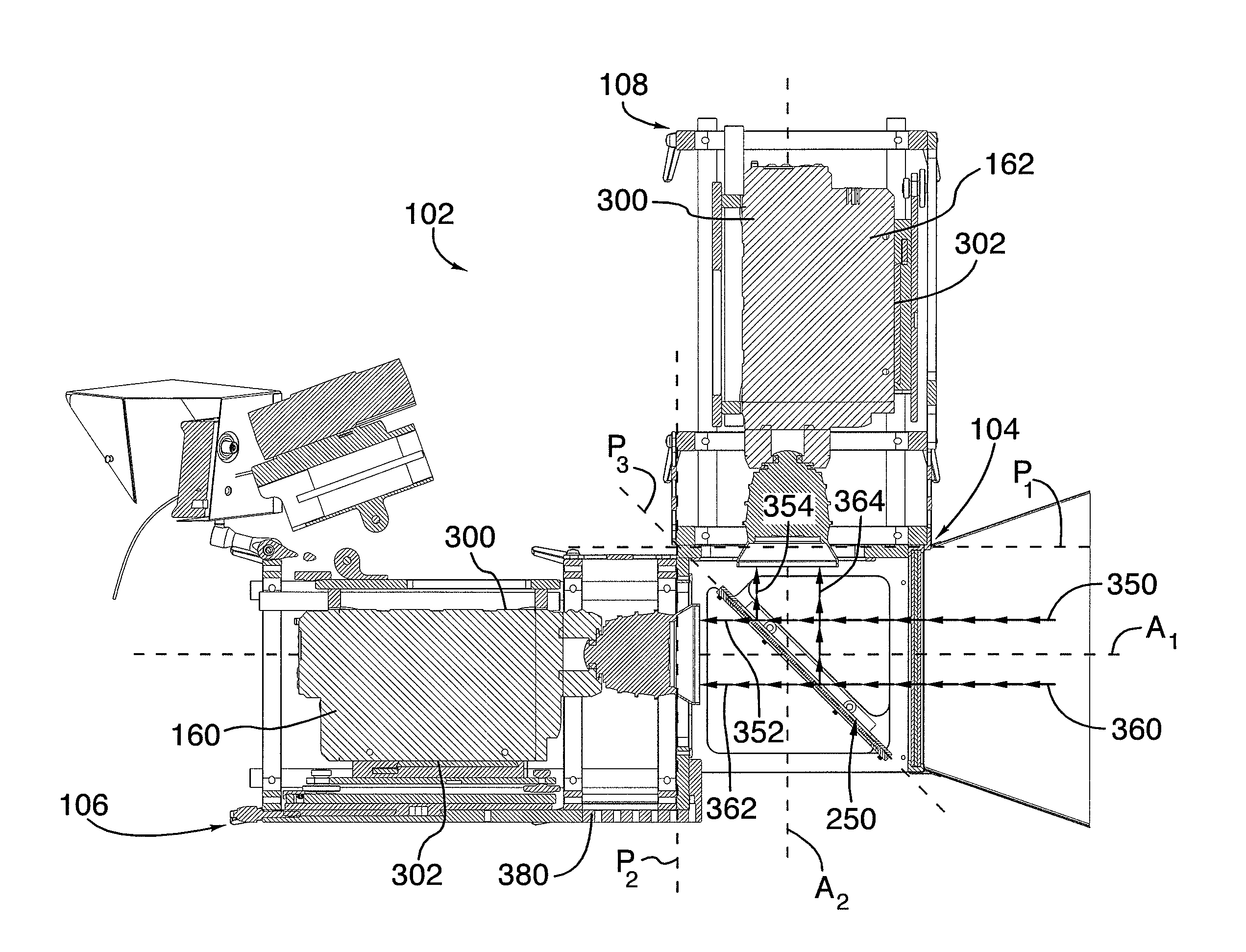
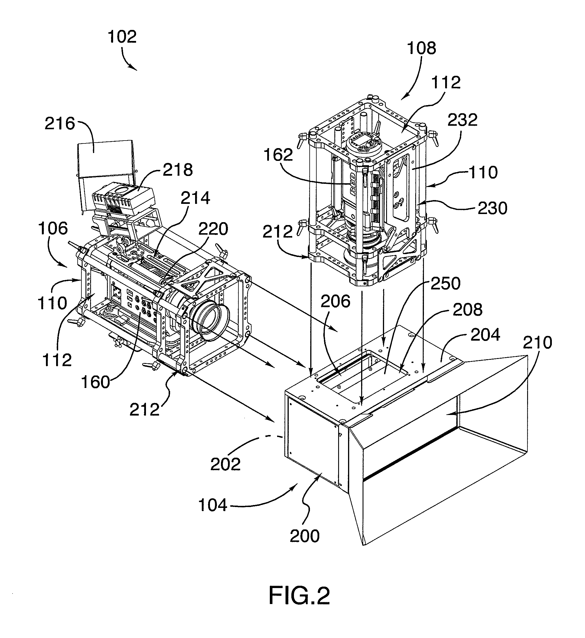
[0045]The stereoscopic camera rig 100 comprises a frame structure 102 pivotably mounted to a stand, or tripod 150. The frame structure 102 comprises a casing 104, a first camera support 106 and a second camera support 108.

[0046]The casing 104 comprises a casing sidewall 200 having first and second planar surfaces 202, 204 which are perpendicular to each other and in which first and second openings 206, 208 are respectively defined. A third opening, or inlet opening 210, is further defined in the casing sidewall 200 in order to allow an incoming light beam...


PUM


Abstract

There is provided a frame structure for stereoscopic imaging. First and second cameras may be mounted to the structure to respectively record first and second images which may be combined to produce a three-dimensional image. The frame structure comprises a casing sized and shaped to receive a beam splitting device therein and first and second camera supports mounted to a sidewall of the casing for respectively holding the first and second cameras. Each camera support comprises an outer frame defining an internal cavity to receive a corresponding camera therein, and attaching means which comprise at least three connecting portions contacting the casing sidewall and positioned around an opening of the casing sidewall. This configuration substantially prevents deformation of the frame structure due to bending.

Description

CROSS-REFERENCE TO RELATED APPLICATIONS[0001]This application is related to U.S. patent application Ser. No. 12 / 128,448 entitled MODULAR STEREOSCOPIC RIG, filed on May 28, 2008, the specification of which is incorporated herein by reference.TECHNICAL FIELD[0002]The invention relates to frame structures for use in imaging. More specifically, the invention pertains to frame structures for stereoscopic imaging.BACKGROUND[0003]Stereoscopic imaging is an imaging technique in which two cameras are used to record three-dimensional visual information. The first camera records a first image and the second camera records a second image which is slightly different from the first image. The first and second images are then combined to produce a three-dimensional image, i.e. a still three-dimensional image if the two cameras are still photography cameras or a three-dimensional video if the two cameras are video cameras.[0004]To perform this technique, the cameras may be arranged in a setting kno...

Claims


Application Information

Patent Timeline
IPC IPC(8): G03B35/08H04N13/239
CPCF16M11/32G03B35/08F16M11/10G03B17/561H04N13/0239H04N2213/001H04N13/239
Inventor ROUTHIER, PIERRE HUGUES
Owner CREAT3
Why Eureka
Try Eureka