
Cleanup additive

a technology of additives and zirconate, applied in the direction of fluid removal, other chemical processes, borehole/well accessories, etc., can solve the problems of difficult crosslinking, poor clean-up properties of zirconate crosslinking polymers, and important risks

Inactive Publication Date: 2001-06-05
SCHLUMBERGER TECH CORP
View PDF20 Cites 222 Cited by
  • Summary
  • Abstract
  • Description
  • Claims
  • Application Information

AI Technical Summary

Benefits of technology

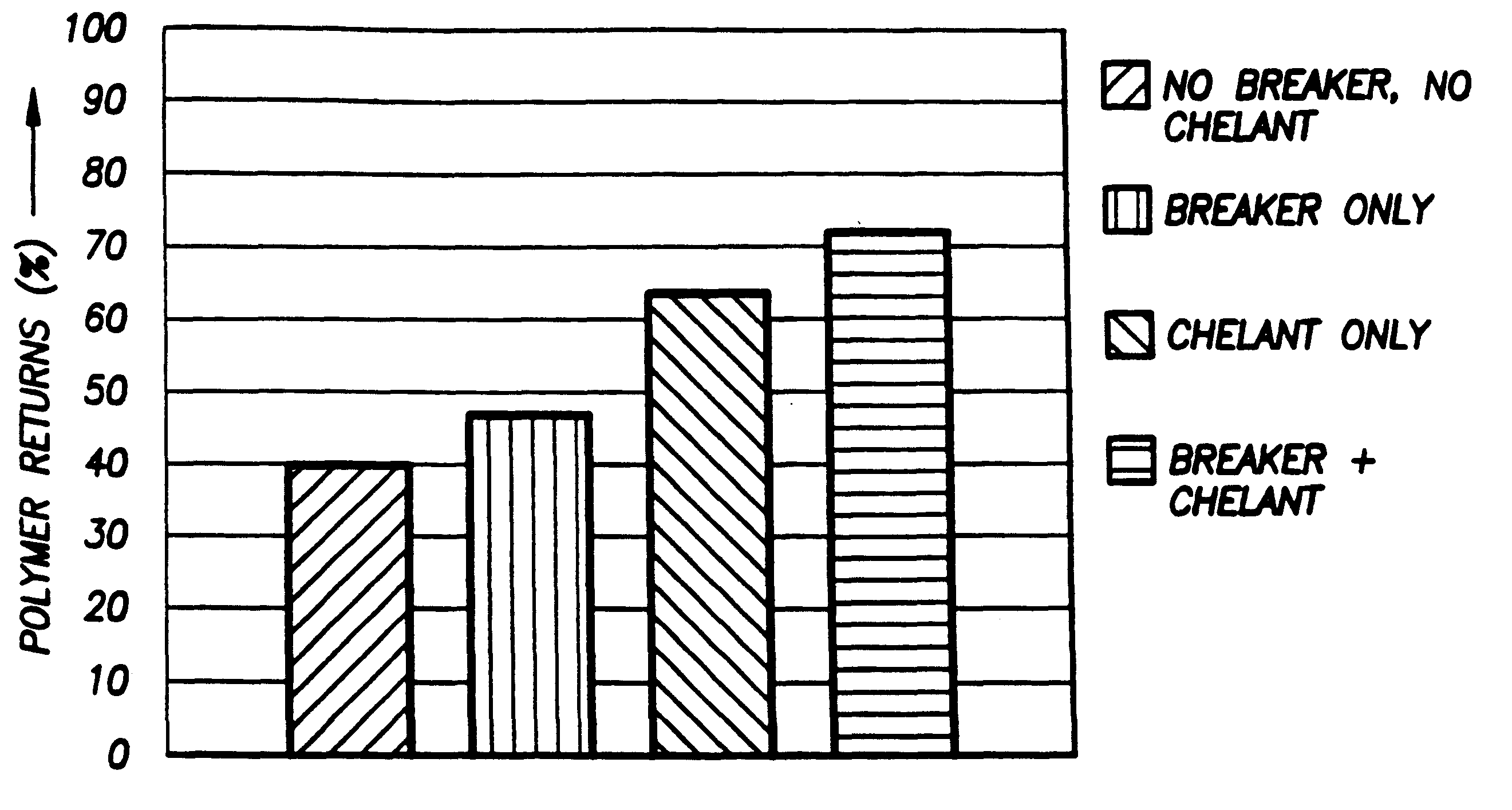
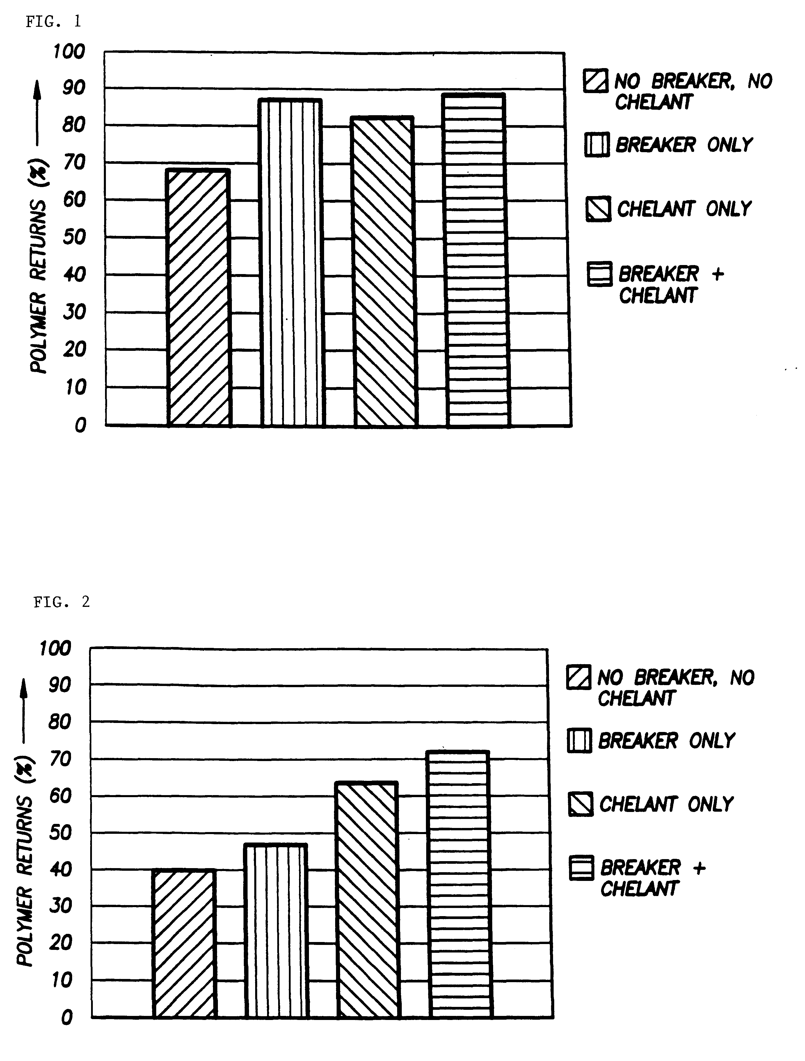
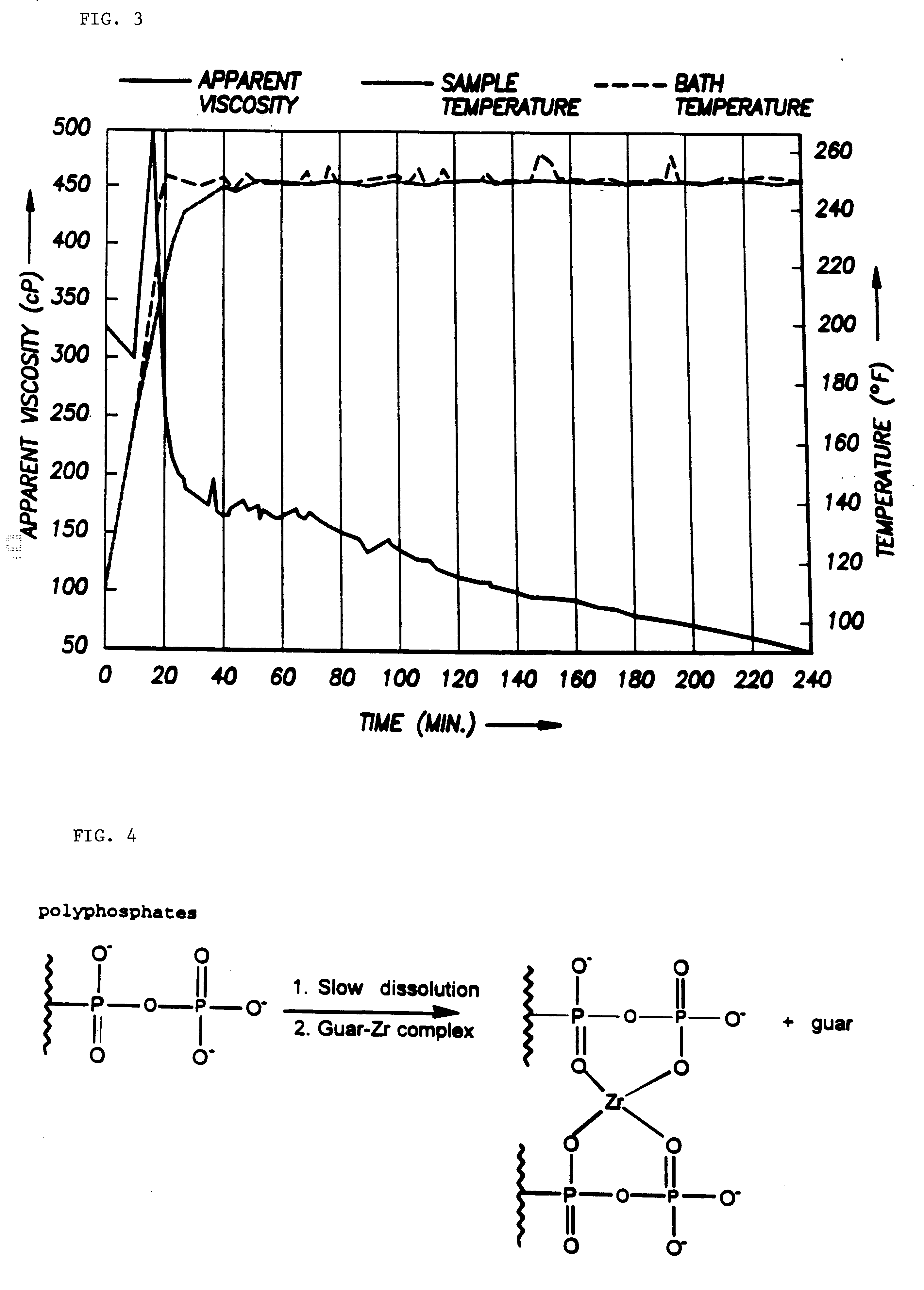
The controlled solubility compound is the cleanup additive. The cleanup additive breaks down the polyvalent metal crosslink to reduce the viscosity of the polymer gel, wherein the polysaccharide is the polymer, and facilitate the removal of the polymer gel after the fracture operation is completed. The controlled solubility compound produces a complexing agent which is able to form a coordination complex with the polyvalent metal ion which is thermodynamically more stable than that which the ion forms with the polymer.

Problems solved by technology

However, if the conventional polymer gel is guar or a substituted guar, an important risk arises when conventional breakers or thermal energy is used to break down the polymer.
Other crosslinks are more difficult to break down and require extra care.
For example, zirconate crosslinked polymers are known to have poor clean-up properties, i.e., they leave behind excess polymer in the formation.
Other metal crosslinks are also difficult to eliminate.
But, zirconium crosslinked polymers continue to present problems for breaking down crosslinks.
Polymer gels which break down prematurely can cause suspended proppant material to settle out of the gel before being introduced a sufficient distance into the produced fracture.
Premature break down can also result in a less than desirable fracture width in the fracture being created.
On the other hand, polymer gels which break down too slowly can cause slow recovery of the polymer from the produced fracture.

Method used


Image

  • Cleanup additive
  • Cleanup additive
  • Cleanup additive

Examples


examples

The following examples merely exemplify various embodiments of the invention. It is understood that the following examples are provided to further illustrate the invention. They do not in anyway limit the scope of the present invention.

Test compositions were prepared with Calgon 29L, sodium calcium magnesium polyphosphate glass, as a 10-30 mesh particle. The Calgon 29L particles dissolved in 140-180.degree. F. water at a rate of 10-20% per month. Because this dissolution rate is too slow for a fracturing fluid cleanup additive, samples of Calgon 29L were hand ground with a mortar and pestle. The ground material was sieved through standard screens to yield samples of various particle size.

The test compositions were tested for rheological properties and conductivity. All compositions were prepared with deionized water. Fann 50's were used to determine whether the compositions could achieve sufficient viscosity to transport proppants and lose sufficient viscosity to break properly. The...


PUM

PropertyMeasurementUnit
Temperatureaaaaaaaaaa
Fractionaaaaaaaaaa
Fractionaaaaaaaaaa

Abstract

According to the present invention, a composition and method for hydraulically fracturing a subterranean formation is provided. The composition comprises an aqueous mixture of a hydrated polysaccharide, preferably a galactomannan gum, the hydrated polysaccharide having a plurality of bonding sites; a crosslinking agent for crosslinking the hydrated polysaccharide at the bonding sites at the conditions of the subterranean formation with a polyvalent metal ion to form a polyvalent metal crosslink, thereby increasing the viscosity of the hydrated polysaccharide; and a controlled solubility compound for releasing a chelating agent for controllably breaking the polyvalent metal crosslink and bonding with the polyvalent metal ion released by breaking the crosslink, thereby decreasing the viscosity of the hydrated polysaccharide. The method comprises the steps of injecting the above-described composition into the subterranean formation at fracturing pressures; allowing the controlled solubility compound to begin breaking the polyvalent metal crosslink, thereby reducing the viscosity of the hydrated polysaccharide and yielding a lower viscosity fluid; and removing the lower viscosity fluid from the subterranean formation.

Description

The present invention relates to polymer returns during flowback after proppant placement with a conventional polymer gel; more particularly, it relates to using chelants to increase the return of crosslinked polymers.DESCRIPTION OF THE PRIOR ARTIn the recovery of hydrocarbons from subterranean formations, it is common practice to subject the formation to a fracturing treatment. The fracturing treatment is designed to provide flow channels in the formation and enhance recovery of the hydrocarbons.During hydraulic fracturing, a fracturing fluid is injected down a wellbore under pressure and forced against the formation strata to penetrate the formation and create flow channels. The fracturing fluid generally contains at least a thickened or gelled aqueous solution and proppant particles. The thickened or gelled aqueous solution must be of sufficient viscosity that it can penetrate the formation strata under the applied pressure.Natural polymers including polysaccharides have been cro...

Claims


Application Information

Patent Timeline
IPC IPC(8): C09K8/68C09K8/60
CPCC09K8/685Y10S507/922
Inventor MITCHELL, THOMAS O.CARD, ROGER J.GOMTSYAN, ARTHUR
Owner SCHLUMBERGER TECH CORP
Learn More