
Fluid Powered Oscillator

a technology of electric oscillators and oscillators, which is applied in the direction of electric generator control, machines/engines, generators/motors, etc., can solve the problems of poor reliability, high maintenance costs, and practical and theoretical problems of rotational mechanical systems, and achieve high reliability.

Inactive Publication Date: 2007-08-02
HAMMIG MARK D
View PDF20 Cites 47 Cited by
  • Summary
  • Abstract
  • Description
  • Claims
  • Application Information

AI Technical Summary

Problems solved by technology

Rotational mechanical systems suffer on both practical and theoretical grounds.
From a practical standpoint, the generators and transmissions common in such systems suffer from relatively poor reliability, and therefore possess high maintenance costs.
Furthermore, for the specific case of a wind turbine mounted horizontally on a tower—the most common configuration—the rotors and the electrical conversion hardware must be installed at elevation, requiring a strong support structure, maintenance duties at hazardous heights, and heavy machinery to accomplish the installation.
Vertically mounted turbines can alleviate some of these concerns, but suffer from poorer aerodynamic performance.
One further disadvantage of a rotational energy-conversion system is that, in principle, the area of its rotor limits its output power.
Among their other problems, charged aerosol generators fail to alleviate the main theoretical disadvantage of rotor designs; that is, the output power still depends on the area subtended by the device.
Such systems fail to substantially decrease the machine complexity, and further, they require a much greater physical footprint for installation, a nontrivial environmental concern given the low energy density inherent to wind flows.

Method used


Image

  • Fluid Powered Oscillator
  • Fluid Powered Oscillator
  • Fluid Powered Oscillator

Examples


Embodiment Construction

[0020]Reference will now be made in detail to the present preferred embodiments of the invention, examples of which are illustrated in the accompanying drawings. Similar or identical structures in the figures are represented by identical callouts.

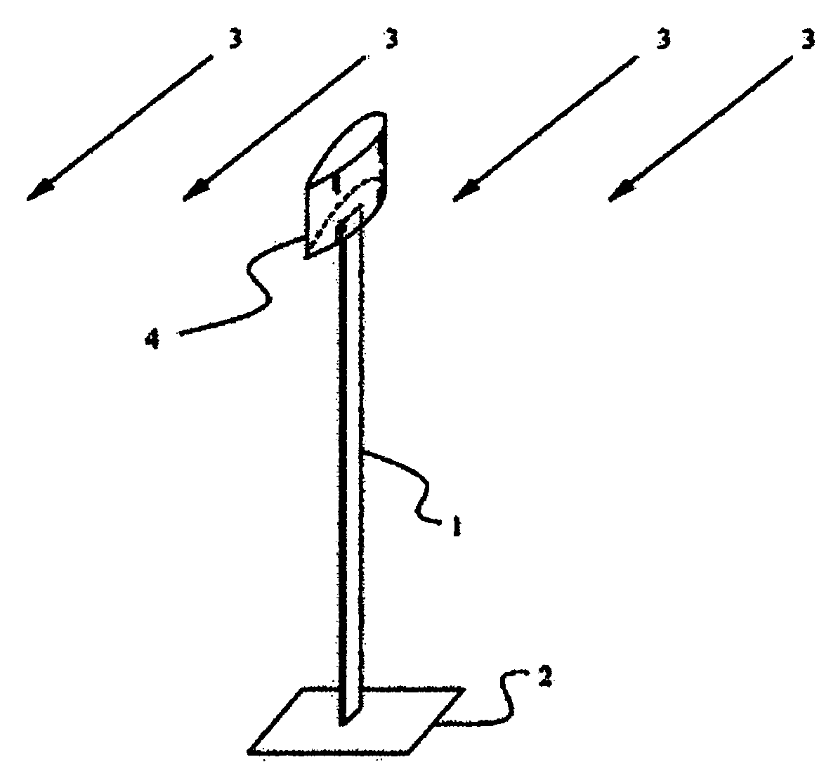
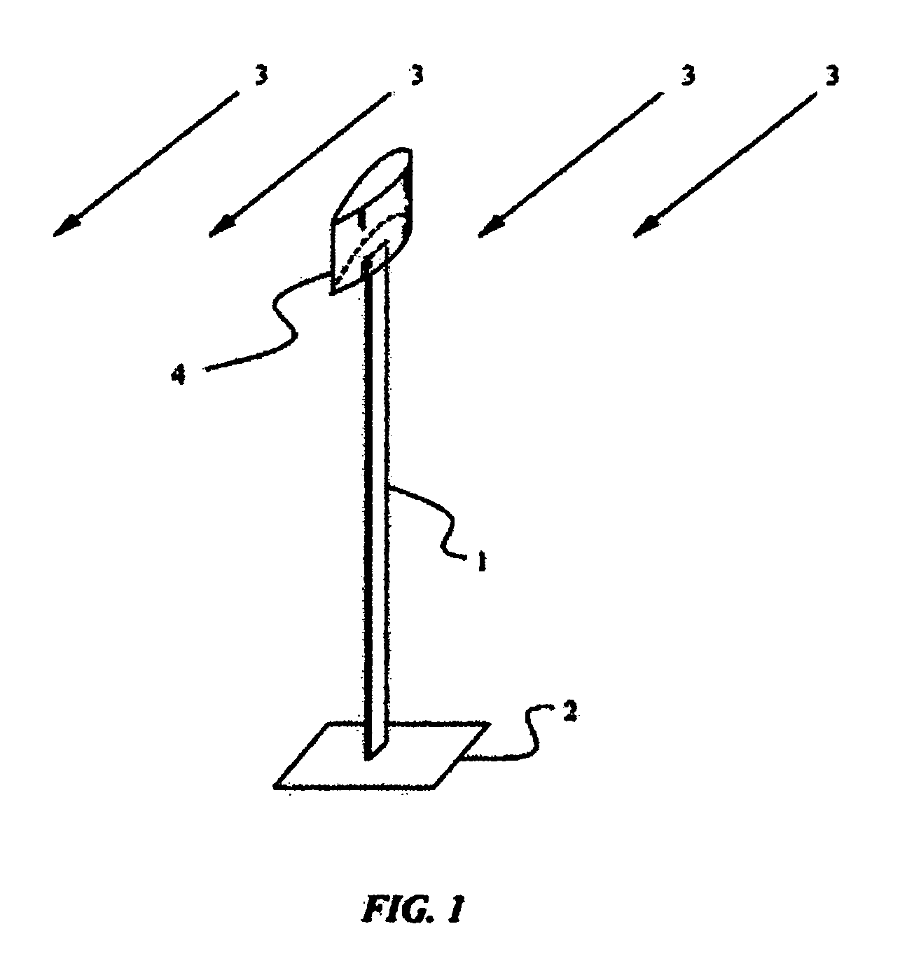
[0021]The present invention will best be understood by reference to FIG. 1, in which the principle components of the invention are illustrated. The mechanical structure of finite stiffness 1 may take many forms; in typical practice, it may take the cantilever shape like that shown in the figure, or it may assume the form of a bridge, or a membrane-element, and will also be referred to as a “lever”. Its most critical feature is that it is capable of deflection in response to environmental influences.

[0022]If structure 1, rigidly mounted to base 2, is placed in air-stream 3, then the structure will deflect in response to the fluid flow in a direction and with a magnitude dependent on the fluid-dynamical forces acting on the body. If the fluid...


PUM


Abstract

A method and device for converting fluidic kinetic energy into oscillatory mechanical motion is disclosed. A mechanical structure of finite stiffness is coupled to a fluid-dynamical control surface the thrust from which is oscillated in direction. The coupling thereby induces oscillations in the structure, the magnitude of which can be controlled by the degree of mechanical resonance between the oscillation rate of the fluidic thrusting and the structure's resonance frequency. The resulting mechanical energy can be converted into electrical energy using either piezo-electric or electromagnetic means.

Description

FIELD OF THE INVENTION[0001]In general, this invention relates to methods and devices that transform fluidic kinetic energy into mechanical motion. More specifically, it relates to those methods and devices that extract either useful work or information from a fluid flow by its coupling to a mechanical system.BACKGROUND OF THE INVENTION[0002]Since antiquity, fluidic forces have been exploited to perform useful work, in such applications as sailing ships and waterwheels. More recently, wind turbines and hydroelectric plants have been used to transform air and water currents, respectively, into electrical power. Typically, that transformation is mechanically elicited by converting the flow into a rotational motion, from which electricity can be generated using well-established technologies.[0003]Mechanical systems have also been used to characterize the nature of the flow; for example, anemometers are commonly used to determine wind speeds and wind vanes allow one to assess the local ...

Claims


Application Information

Patent Timeline
Patent Type & Authority Applications(United States)
IPC IPC(8): H02P9/04F03B13/00
CPCF03B17/06F03D5/06Y02E10/70H02N2/185Y02E10/28F05B2260/407Y02E10/20
Inventor HAMMIG, MARK D.
Owner HAMMIG MARK D
Learn More