Control panel device and display

Inactive Publication Date: 2007-08-02
SONY CORP
View PDF0 Cites 4 Cited by
  • Summary
  • Abstract
  • Description
  • Claims
  • Application Information

AI Technical Summary

Benefits of technology

[0008]In the control panel device 101 shown in FIGS. 1A and 1B, the display substrate 111 is provided separately from the main substrate 106, and the main substrate 106 and the display substrate 111 are connected to each other through a harness, connector or the like (not shown), and, therefore, the cost of the control pane

Problems solved by technology

In addition, laying the harness around and the like lead to complication of the configuration of the in

Method used


Image

  • Control panel device and display
  • Control panel device and display
  • Control panel device and display

Examples


Embodiment Construction

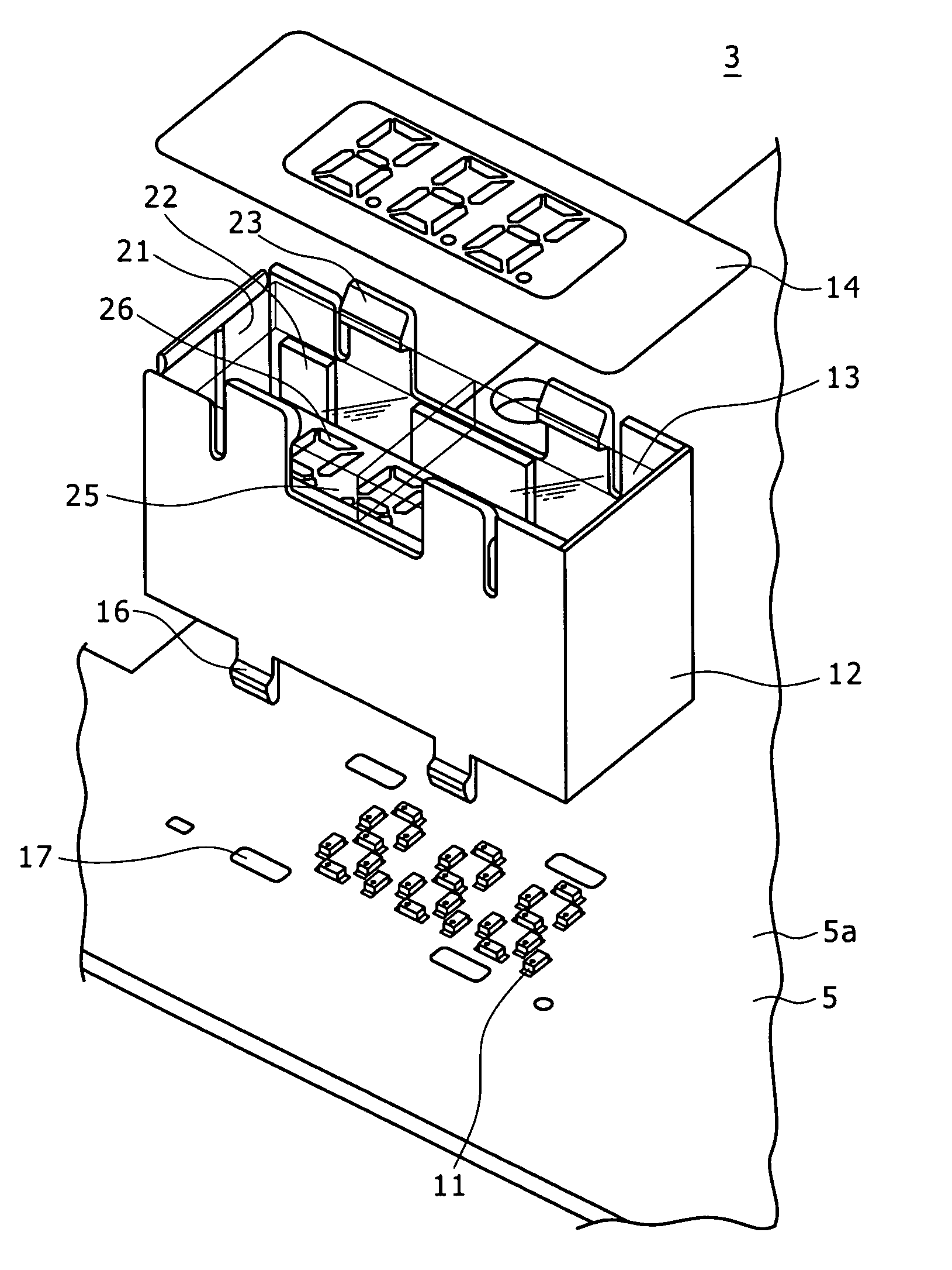
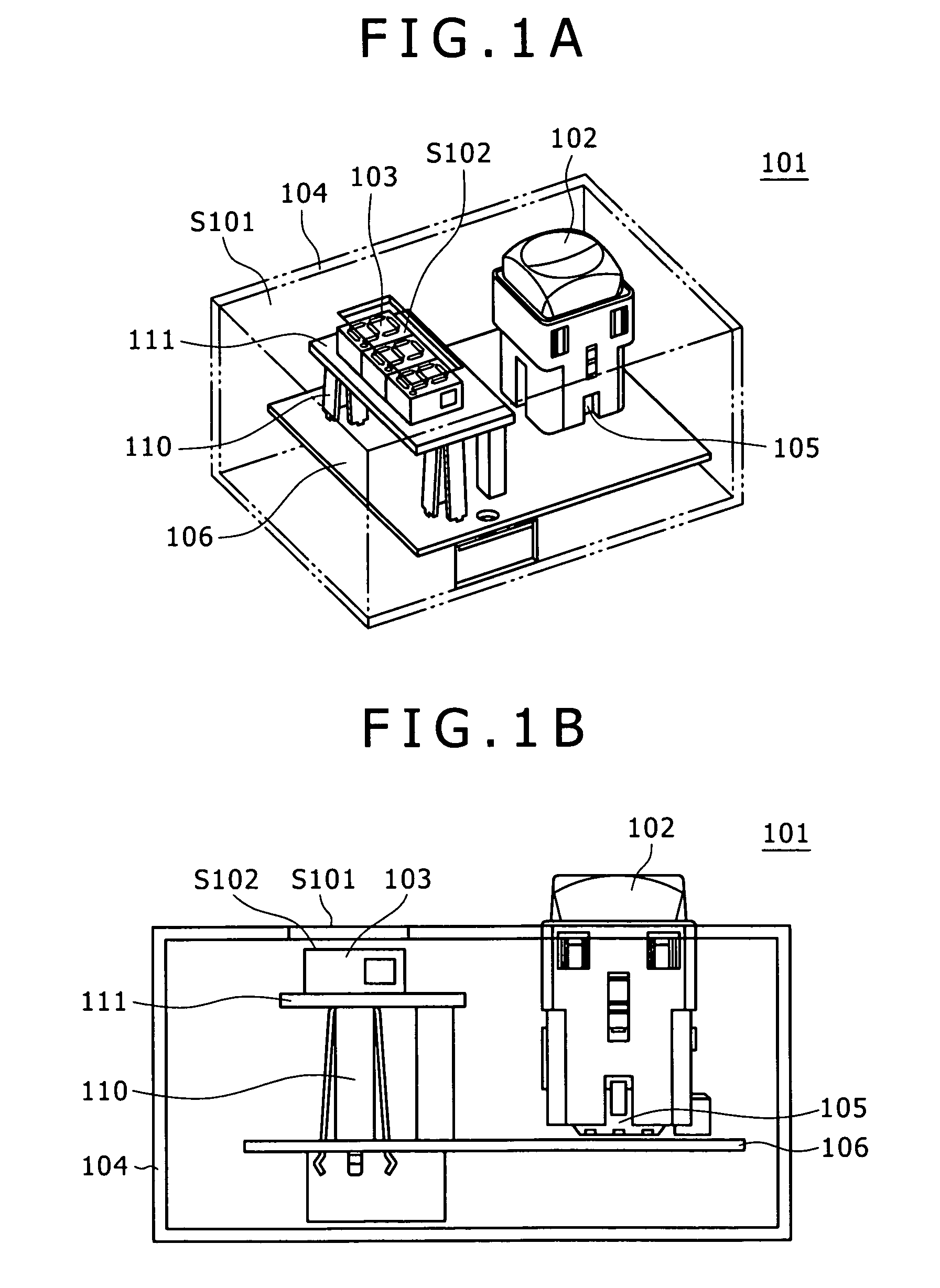
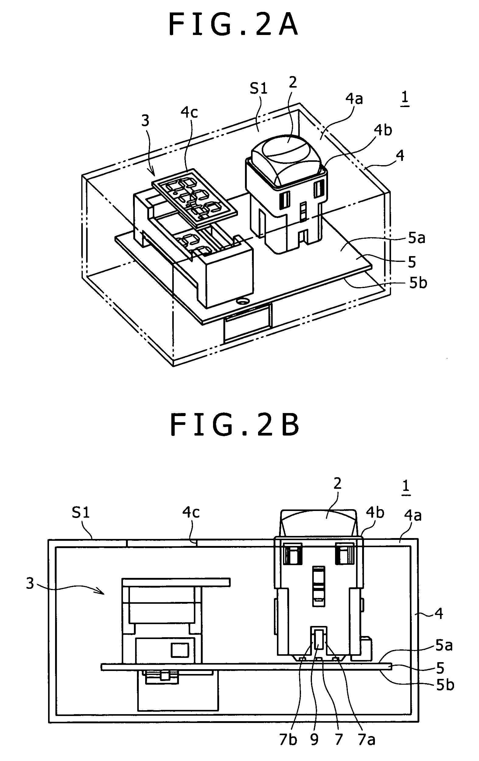
[0027]FIG. 2A is a perspective view which partly perspectively shows a control panel device 1 according to an embodiment of the present invention, and FIG. 2B is a side view which partly perspectively shows the control panel device 1. The control panel device 1 is for controlling the operation of a controlled system by depressing of a keytop 2, and information according to the depressing operation is displayed on a display 3. Incidentally, the keytop 2 is an example of the operating member.

[0028]The control panel device 1 has a casing 4, and a substrate 5 is provided in the inside of the casing 4. The casing 4 is formed, for example, of a resin or a metal. The casing 4 is, for example, a regular parallelepiped in shape, and has a flat plate-like panel section 4a constituting a surface on the upper side with respect to the figure. The panel section 4a is provided with an opening part 4b for exposing the keytop 2 at a panel surface S1 on the casing outer side (the opposite side of the...


PUM


Abstract

Disclosed herein is a control panel device includes: a substrate; a panel section disposed oppositely to one principal surface of the substrate, with a predetermined spacing therebetween; an operating member exposed at a panel surface, on the opposite side of the substrate, of the panel section; a detecting element provided on the substrate and operative to detect an operation on the operating member; a display configured to display information on the panel surface; and a control unit configured to control operations of the display based on a signal obtained according to detection by the detecting element; wherein the display includes a light emitting element; a shaping member; a rod lens array; and a rear screen.

Description

CROSS REFERENCES TO RELATED APPLICATIONS[0001]The present invention contains subject matter related to Japanese Patent Application JP 2006-020590 filed in the Japanese Patent Office on Jan. 30, 2006, the entire contents of which being incorporated herein by reference.BACKGROUND OF THE INVENTION[0002]1. Field of the Invention[0003]The present invention relates to a control panel device and a display.[0004]2. Description of the Related Art[0005]In a control panel, generally, a display capable of displaying numerical values and characters, such as a liquid crystal display and a segment display, is provide for permitting the user to visually check the operating conditions of a controlled system, etc. FIG. 1A is a perspective view for partly perspectively showing a control panel device 101 according to the related art, and FIG. 1B is a side view for partly perspectively showing the control panel device 101. The control panel device 101 is for controlling the operations of a controlled sy...

Claims


Application Information

Patent Timeline
IPC IPC(8): G09G3/04
CPCG09G3/14G09F9/33
Inventor MIYANO, HIDEO
Owner SONY CORP
Why Eureka
Try Eureka