
Sterilizing apparatus

Pending Publication Date: 2022-01-13
SHINKO SANGYO CO LTD
View PDF0 Cites 0 Cited by
  • Summary
  • Abstract
  • Description
  • Claims
  • Application Information

AI Technical Summary

Benefits of technology

The present patent is about a sterilizing apparatus that can be used to spray a medical fluid containing alcohol into a target space to sterilize it. The apparatus includes a container for the medical fluid, a gas cylinder for supplying carbon dioxide gas, and a spray gun. The carbon dioxide gas is injected from the spray gun and the medical fluid is sucked up and converted into particulate form. The apparatus can be adapted to different target spaces and can be easily moved around. The technical effects of the invention include the ability to efficiently and successfully sterilize various target spaces, including clean rooms, kitchens, and patient's rooms, with minimal burden on the operator.

Problems solved by technology

The medical fluid in the form of particles to be sprayed is composed mainly of high concentration alcohol and thus has the risk of catching fire and causing an explosion.
This saves time and effort required for a post-sterilizing process including wiping.
Unfortunately, the sterilizing apparatus is not intended to meet different needs for different target spaces.
The operator, however, needs to wear protectors, such as a mask and goggles, which increases the burden on the operator.

Method used


Image

  • Sterilizing apparatus
  • Sterilizing apparatus
  • Sterilizing apparatus

Examples


embodiment 1

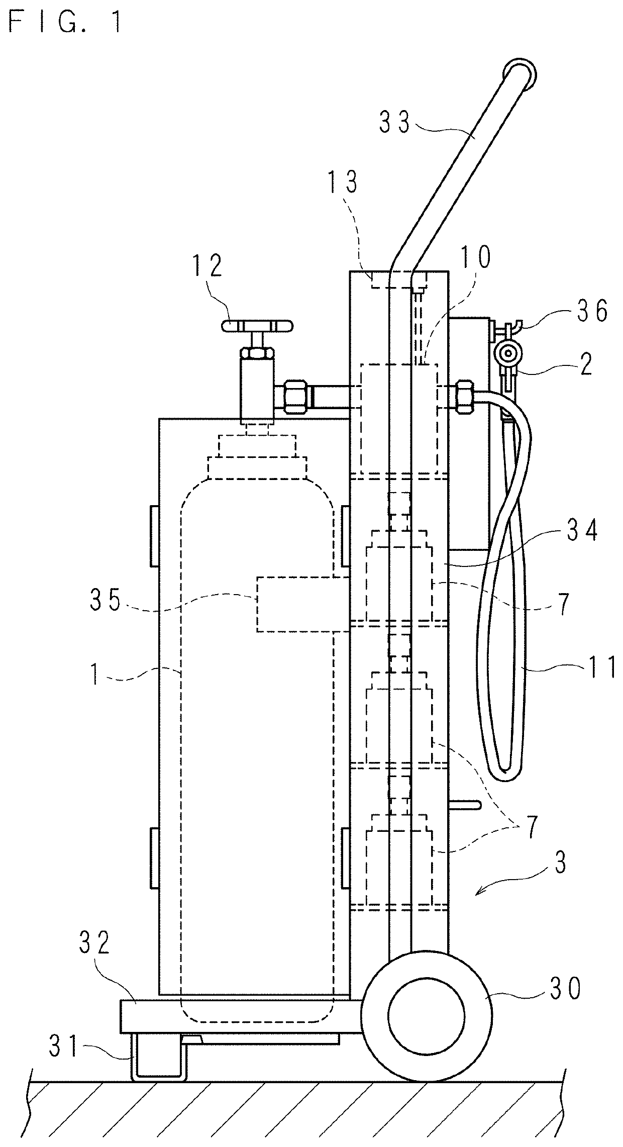
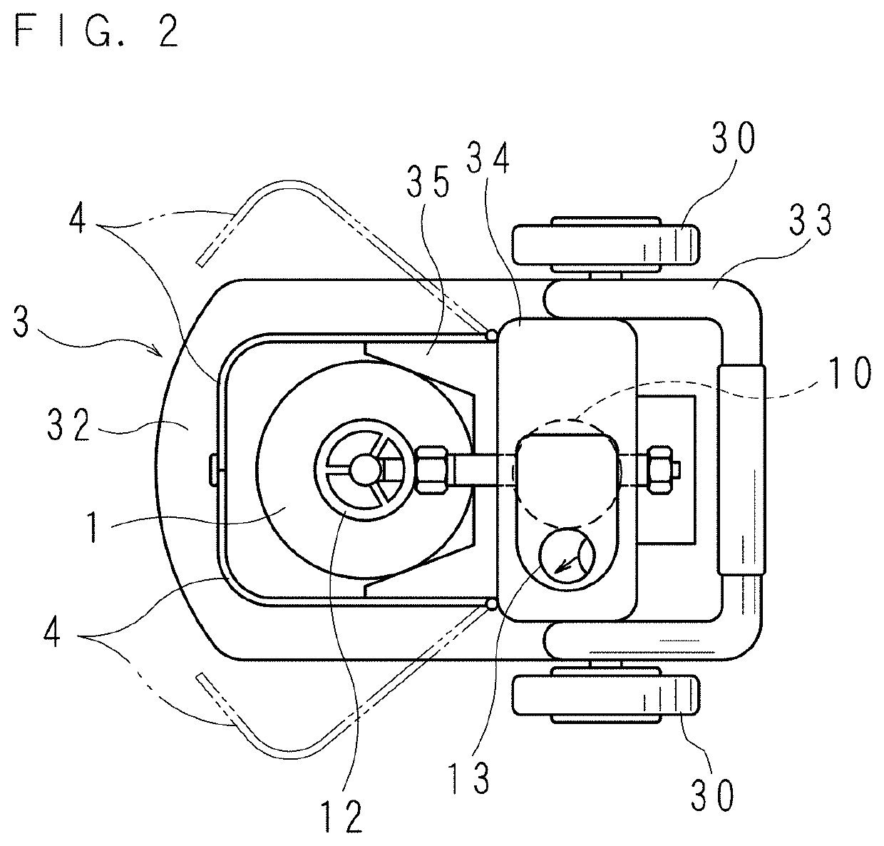
[0027]FIG. 1 is a side view of a sterilizing apparatus according to Embodiment 1. FIG. 2 is a plan view of the sterilizing apparatus as viewed from above.

[0028]As illustrated in FIGS. 1 and 2, the sterilizing apparatus according to Embodiment 1 includes: a gas cylinder 1 filled with pressurized carbon dioxide gas serving as a carrier gas; and a spray gun 2 connected to a discharge port of the gas cylinder 1 through a pressure reducing valve 10 and a gas hose 11.

[0029]The gas cylinder 1 is installed on a cart 3. The cart 3 includes a base 32 supported by a pair of wheels 30, 30 and a supporting leg 31 such that the base 32 is substantially parallel to a floor surface. The base 32 is provided with a gripping pipe 33 extending vertically upward from locations on the wheels 30, 30. A holding box 34 is provided between legs of the gripping pipe 33.

[0030]The gas cylinder 1 is placed on a central region of the upper surface of the base 32, with the discharge port facing upward. An intermed...

embodiment 2

[0056]A sterilizing apparatus according to Embodiment 2 is structured to be able to sterilize the inside of a target space in an unlimited manner. FIG. 6 is a schematic diagram illustrating an overall structure of the sterilizing apparatus according to Embodiment 2. Similarly to Embodiment 1, the sterilizing apparatus illustrated in FIG. 6 includes: a gas cylinder 1 filled with pressurized carbon dioxide gas; and a spray gun 2 to spray a medical fluid using, as a carrier gas, the carbon dioxide gas supplied from the gas cylinder 1. The sterilizing apparatus according to Embodiment 2 further includes: a control panel 8 for operating the sterilizing apparatus; and a mounting stand 9 for the spray gun 2.

[0057]Similarly to Embodiment 1, the gas cylinder 1 having its periphery surrounded by an exterior cover 4 is installed on a cart 3 and is suitably movable together with the cart 3. A discharge port on the upper end of the gas cylinder 1 is connected with a first end of an output hose 1...


PUM


Abstract

An example sterilizing apparatus comprises a medical fluid container storing a medical fluid containing alcohol, a gas cylinder filled with pressurized carbon dioxide gas, and a spray gun connected with the medical fluid container and the gas cylinder. The sterilizing apparatus being configured to spray the medical fluid into a target space under action of the carbon dioxide gas injected from a tip nozzle of the spray gun. The sterilizing apparatus further comprises a control valve to increase and / or decrease an amount of the carbon dioxide gas to be injected, thus adjusting an amount of the medical fluid to be sprayed.

Description

CROSS-REFERENCE TO RELATED APPLICATIONS[0001]This non-provisional application claims priority under 35 U.S.C. § 119 to Japanese Patent Application No. 2020-120180 filed in Japan on Jul. 13, 2020, the entire contents of which are hereby incorporated by reference.FIELD[0002]The present disclosure relates to sterilizing apparatuses.BACKGROUND AND SUMMARY[0003]There has been a sterilizing apparatus to convert a medical fluid composed mainly of alcohol into particulates and spray the particulate medical fluid into a target space so as to sterilize the target space.[0004]For example, the apparatus includes a spray gun such as those used widely for coating. A medical fluid tank storing the above-mentioned medical fluid is attached to the spray gun. A gas cylinder storing carbon dioxide gas serving as a carrier gas is connected to the spray gun. The carbon dioxide gas is injected from a tip nozzle of the spray gun. Under the action of negative pressure generated during this injection, the m...

Claims


Application Information

Patent Timeline
IPC IPC(8): A61L2/22A61L2/26A61L2/24
CPCA61L2/22A61L2/26A61L2202/15A61L2202/25A61L2202/16A61L2/24A61L2202/11A61L2202/14
Inventor ONO, MOTOTSUGU
Owner SHINKO SANGYO CO LTD
Learn More