This helps you quickly interpret patents by identifying the three key elements:
Problems solved by technology
Method used
Benefits of technology
Benefits of technology
The technology described in this patent improves the quality of images captured by an endoscopic system without adding extra work to the central processing unit (CPU) and making the endoscope larger.
Problems solved by technology
Since the two images are displayed on a display, in this case, the individual images are displayed in small sizes, resulting in a reduction in observing capability.
However, the endoscope disclosed in Japanese Patent Laid-Open No. 2014-228851 requires a lot of processing time, imposing a large burden on a controller such as a CPU or the like, in order to combine the images captured at the different focal positions.
Since the endoscope needs to display captured images in real time, it is difficult to apply the image combining process that requires a lot of processing time.
The large-diameter distal-end portion tends to impair the ability of the endoscope to reach and observe details in the object to be observed.
Method used
Image
Click on the blue label to locate the original text in one second.
Reading with bidirectional positioning of images and text.
Examples
first embodiment
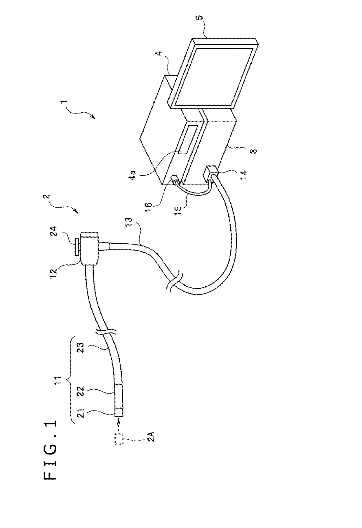
[0033]FIG. 1 is a configuration view illustrating a configuration of an endoscopic system according to a first embodiment. As illustrated in FIG. 1, the endoscopic system, denoted by1, according to the present embodiment includes an endoscope 2, a light source device 3 to which the endoscope 2 is connected, a main device 4 including a camera control unit (hereinafter referred to as “CCU”), etc., and a display 5. The display 5 is defined as a display device that displays information in pictorial form and the likes.
[0034]The endoscope 2 is an electronic endoscope having an insertion portion 11 that is slender and flexible, a manipulator 12 connected to the proximal end of the insertion portion 11, and a universal cable 13 extending from the manipulator 12. An optical adapter 2A can be mounted on the distal end of the insertion portion 11.
[0035]A connector 14 that is disposed on the distal end of the universal cable 13 extending from the manipulator 12 can be detachably mounted on the ...
modification 3
[0096]Next, modification 3 of the first embodiment will be described hereinafter.
[0097]According to the first embodiment, as illustrated in FIG. 6, the distance is measured each time to determine whether to switch the displayed image. However, for the purpose of carrying out the process of determining whether to switch the displayed image, since it is necessary to switch between the optical paths to acquire captured left and right images and to perform a processing operation for measuring the distance, some processing time needs to be spent. If the endoscopic system 1 is to operate in a live mode, the frame rate is lowered. In order to prevent the frame rate from being lowered, the processing operation for measuring the distance in steps S4 and S5 in FIG. 6 may be carried out once in a plurality of sessions, i.e., in a plurality of frames, and the process of determining whether to switch the displayed image in step S6 in FIG. 6 may be carried out once in a plurality of sessions.
second embodiment
[0098]Next, a second embodiment will be described hereinafter.
[0099]According to the first embodiment, the endoscopic system for performing switching-type stereo measurement to switch between and acquire left and right images has been described. According to a second embodiment, an endoscopic system for performing simultaneous stereo measurement to acquire left and right images simultaneously will be described. The endoscopic system according to the second embodiment has the same overall configuration as the first embodiment.
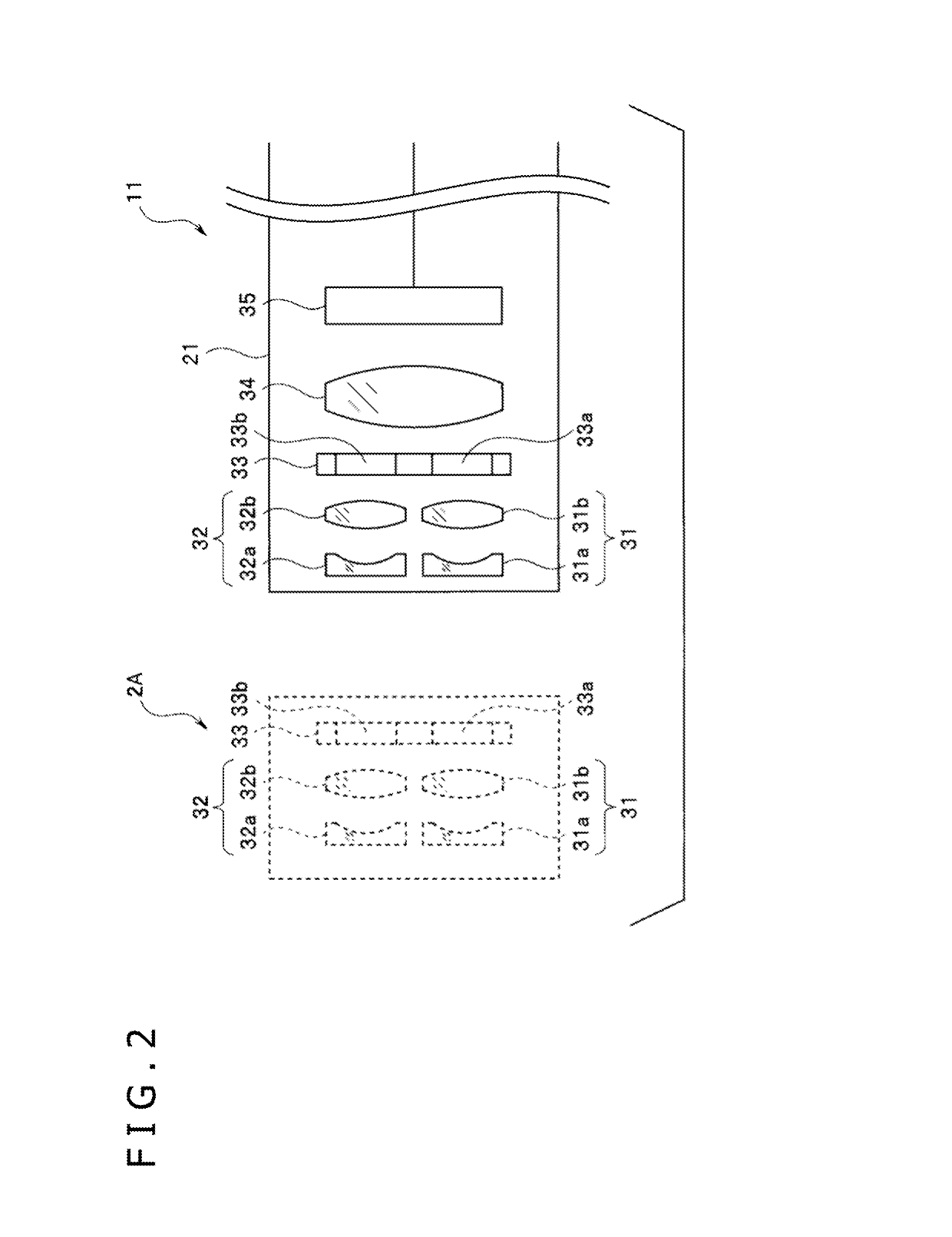
[0100]FIG. 10 is a view illustrating a configuration of an optical system in the distal-end portion of an insertion portion according to the second embodiment. Those parts illustrated in FIG. 10 which are identical to those illustrated in FIG. 2 are denoted by identical numeral references, and will not be described in detail hereinafter.
[0101]As illustrated in FIG. 10, the insertion portion 11 has a distal-end portion 21a that is free of the light shield 33 in t...
PUM
Abstract
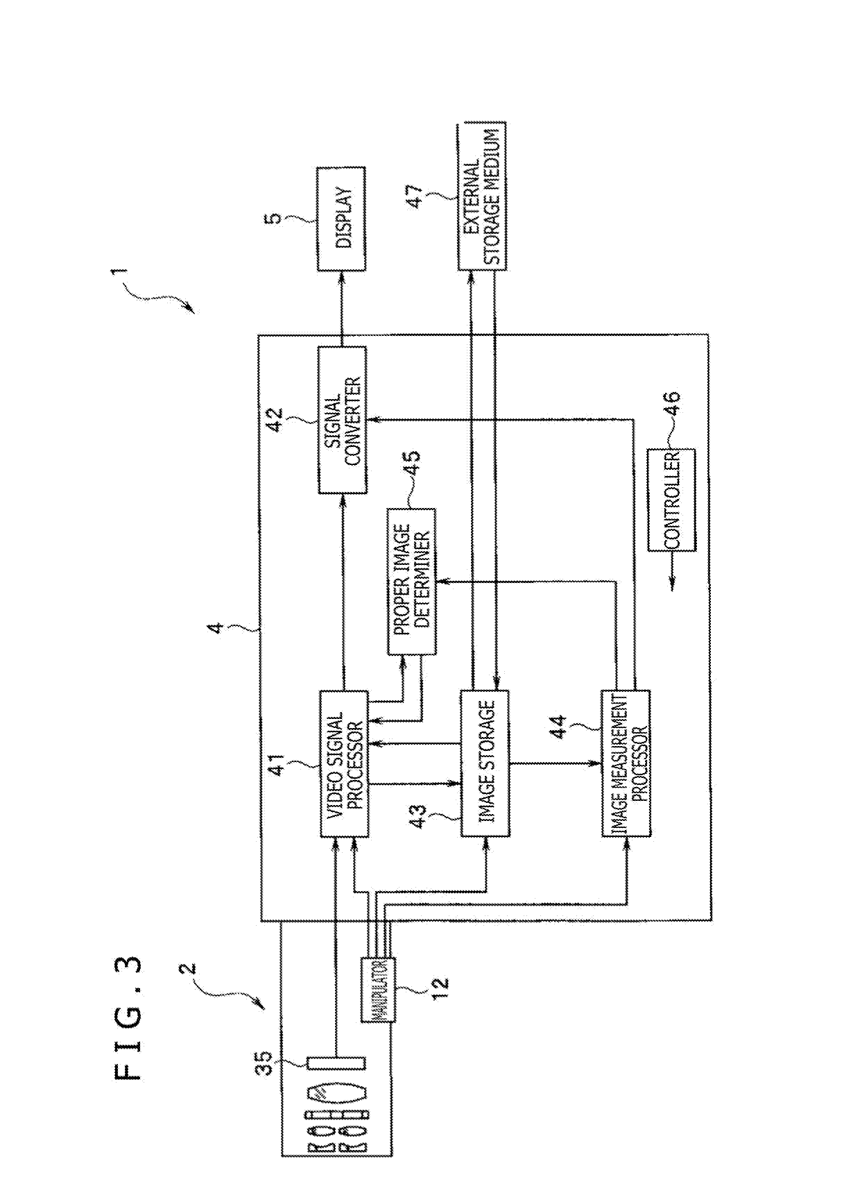
An endoscopic system includes a left optical system having a first focal position, a right optical system having a second focal position that is different from the first focal position. An image capturing device generates a first image and a second image respectively from images of a subject that are obtained by the left optical system and the right optical system. A display device displays the first image or the second image. A proper image determiner determines the magnitude relationship between the position of the subject in a predetermined area displayed on the display device and at least one threshold value Th is established between the first focal position and the second focal position. A video signal processor switches to the first image or the second image depending on a determined result from the proper image determiner and displays the image on the display device.
Description
CROSS-REFERENCE TO RELATED APPLICATIONS[0001]This application is a continuation application of PCT Application No. PCT / JP2017 / 013938 filed on Apr. 3, 2017, which in turn claim priority to the Japanese Patent Application No. 2016-122747 filed on Jun. 21, 2016 in Japan which is hereby incorporated by reference in its entirety.TECHNICAL FIELD[0002]The technology disclosed herein relates to an endoscopic system, and more particularly to an endoscopic system for acquiring images from different optical paths.DESCRIPTION OF THE RELATED ART[0003]Endoscopes have widely been used in the medical field and the industrial field, etc. Endoscopic systems generally include an endoscope for capturing an image of a subject in a body, a video processor for generating an observational image of the subject whose image has been captured by the endoscope. And a monitor displays the observational image generated by the video processor. Particularly, industrial endoscopes are widely used to observe and insp...
Claims
Application Information
Patent Timeline
Application Date:The date an application was filed.
Publication Date:The date a patent or application was officially published.
First Publication Date:The earliest publication date of a patent with the same application number.
Issue Date:Publication date of the patent grant document.
PCT Entry Date:The Entry date of PCT National Phase.
Estimated Expiry Date:The statutory expiry date of a patent right according to the Patent Law, and it is the longest term of protection that the patent right can achieve without the termination of the patent right due to other reasons(Term extension factor has been taken into account ).
Invalid Date:Actual expiry date is based on effective date or publication date of legal transaction data of invalid patent.

