
Droplet ejection apparatus

a technology of droplets and ejection tubes, which is applied in the direction of printing, other printing apparatus, etc., can solve the problems of difficult to shorten the total time for carrying out recording processes, the ink vibration does not easily settle down, etc., and achieves the effect of shortening the total time, shortening the interval, and reducing the liquid consumption amoun

Active Publication Date: 2007-08-02
BROTHER KOGYO KK
View PDF4 Cites 7 Cited by
  • Summary
  • Abstract
  • Description
  • Claims
  • Application Information

AI Technical Summary

Benefits of technology

[0011]It is therefore an object of the invention to provide a droplet ejection apparatus capable of performing a restoring operation such as a preparatory ink-droplet ejection, i.e., so-called “the flushing operation” as well as shortening a time for carrying out the recording process.
[0013]In the conventional droplet ejection apparatus disclosed in JP-A-9-295411, the operation by the first voltage applying means is performed after the operation by the second voltage applying means is performed, whereby the vibration of the liquid such as ink does not easily settle down, as described hereinabove. In contrast, in the droplet ejection apparatus according to the present invention, the first operation is initially performed such that the droplets are ejected from each of the plurality of the nozzles, then the second operation is subsequently performed such that the droplet is not ejected from each of the plurality of the nozzles. Therefore, after the restoring operation for restoring the droplet ejection performance of the recording head is performed, namely, after both of the first operation and the second operation are performed in order, the vibration of the liquid settles down in a short time, whereby it is possible to shorten an interval between the flushing operation and the recording operation to be subsequently performed. In consequence, it is effective to shorten a total time for carrying out the recording process.
[0014]Moreover, since the second operation for outputting non-ejection drive pulses by which the droplet can not be ejected in the restoring operation is performed, together with the first operation for outputting ejection drive pulses by which the droplet can be ejected, it is capable of greatly reducing a consumption amount of the liquid, as compared with an another type of the restoring operation in which only the first operation is performed. That is, since the first operation and the second operation are performed in the above-described order in the restoring operation, it is possible to reduce a total number of the ejection drive pulses by which the droplets are ejected and which are to be outputted in the restoring operation, whereby it is effective to reduce the consumption amount of the liquid such as ink.

Problems solved by technology

In this state, the vibration of the ink does not easily settle down.
Thus, it is difficult to shorten a total time for carrying out the recording process since it takes much time for the vibrated ink to settle down after the flushing operation.

Method used


Image

  • Droplet ejection apparatus
  • Droplet ejection apparatus
  • Droplet ejection apparatus

Examples


Embodiment Construction

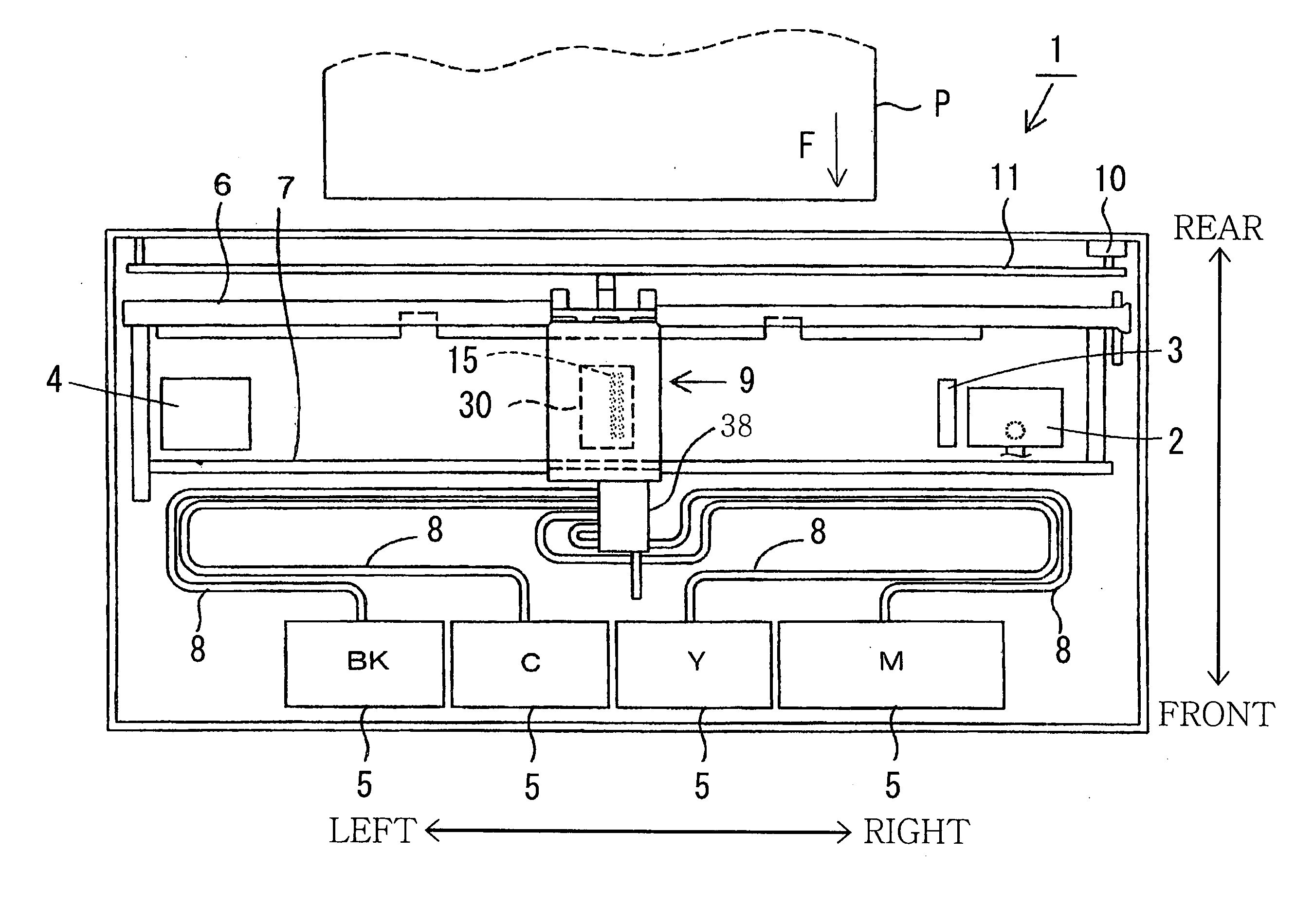
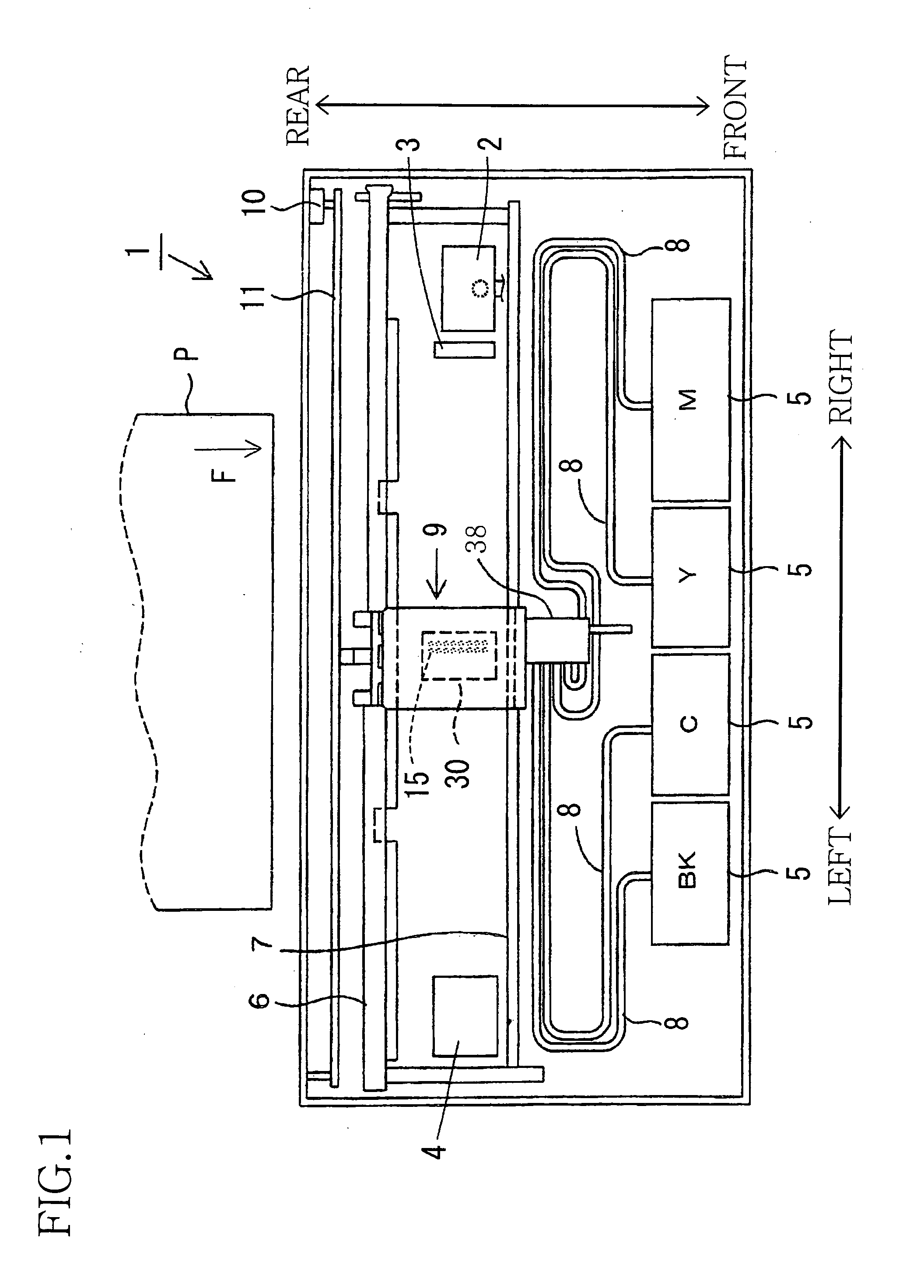
[0025]Hereinafter, there will be described a preferred embodiment of the present invention by reference to the drawings. FIG. 1 is a plan view of an inkjet printer 1 employing a droplet ejection apparatus as one embodiment of the present invention. In a description hereinafter, a surface of a recording head 30 in which a plurality of the nozzles 15 are formed is defined as a lower surface and a direction in which an ink is ejected from the plurality of nozzles 15 is defined as a downward direction. A direction of the recording head 30 which is opposite to the downward direction is defined as an upward direction and a surface of the recording head 30 which is opposed to the lower surface thereof is defined as an upper surface thereof. Moreover, a direction toward a leftward end of the plan view of FIG. 1 is defined as a leftward direction, a direction toward a rightward end of FIG. 1 is defined as a rightward direction. A lower end and an upper end of FIG. 1 are defined as a front si...


PUM


Abstract

A droplet ejection apparatus comprises: (a) a recording head including a nozzle from which a droplet of a liquid is ejected, (b) a pressure chamber which is filled with the liquid and whose volume is changeable for ejecting the droplet from the nozzle, and (c) an actuator which changes the volume of the pressure chamber by a drive pulse inputted thereto; and an operating device which outputs the drive pulse to the actuator and which is capable of performing a restoring operation for restoring a droplet ejection performance of the recording head. The restoring operation includes: a first operation for outputting, a plurality of times, an ejection drive pulse as the drive pulse by which the droplet can be ejected; and a second operation for outputting, a plurality of times, a non-ejection drive pulse as the drive pulse by which the droplet can not be ejected, the second operation being performed following the first operation.

Description

[0001]The present application is based on Japanese Patent Application No. 2006-018516 filed on Jan. 27, 2006, the contents of which are incorporated herein by reference.BACKGROUND OF THE INVENTION[0002]1. Field of the Invention[0003]The present invention relates to a droplet ejection apparatus, such as an inkjet printer, capable of ejecting droplets of a liquid such as ink, and more particular to an operation of the droplet ejection apparatus for preventing a poor droplet ejection performance due to drying of the liquid contained inside of a nozzle.[0004]2. Discussion of Related Art[0005]There has conventionally been known an inkjet printer including a recording head which is mounted on a carriage and which has a plurality of nozzles provided on a lower surface thereof. In the conventional inkjet printer, while the recording head is reciprocated in a recording area, a recording operation in which droplets of ink are ejected onto a recording medium is performed so as to record an ima...

Claims


Application Information

Patent Timeline
IPC IPC(8): B41J29/38
CPCB41J2/04551B41J2/04581B41J2/16526B41J2/04596B41J2/04588
Inventor SEKIGUCHI, YASUHIRO
Owner BROTHER KOGYO KK
Learn More