Flat projection television

a projection television and flat technology, applied in the field of projection television sets, can solve the problems of difficult folding of optics in boxes or enclosures having thickness or depth on the order of conventional plasma television sets

Inactive Publication Date: 2007-08-02
MITSUBISHI ELECTRIC US
View PDF9 Cites 2 Cited by
  • Summary
  • Abstract
  • Description
  • Claims
  • Application Information

AI Technical Summary

Problems solved by technology

The proper folding of the optics in a box or enclosure having a thickness or depth on the order of conventional plasma television sets has proven to be difficult.

Method used


Image

  • Flat projection television
  • Flat projection television
  • Flat projection television

Examples


Embodiment Construction

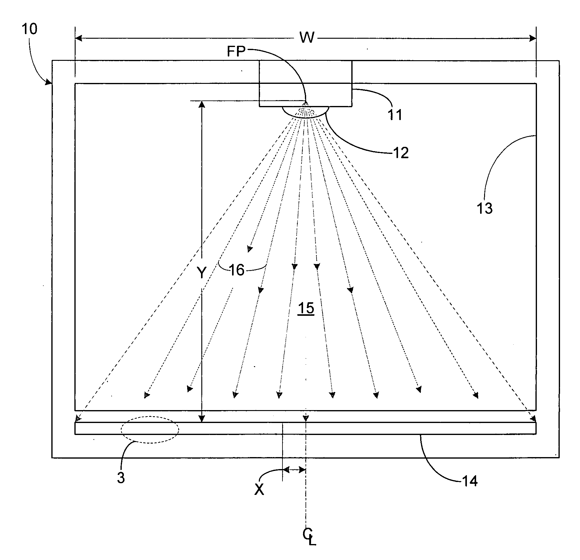
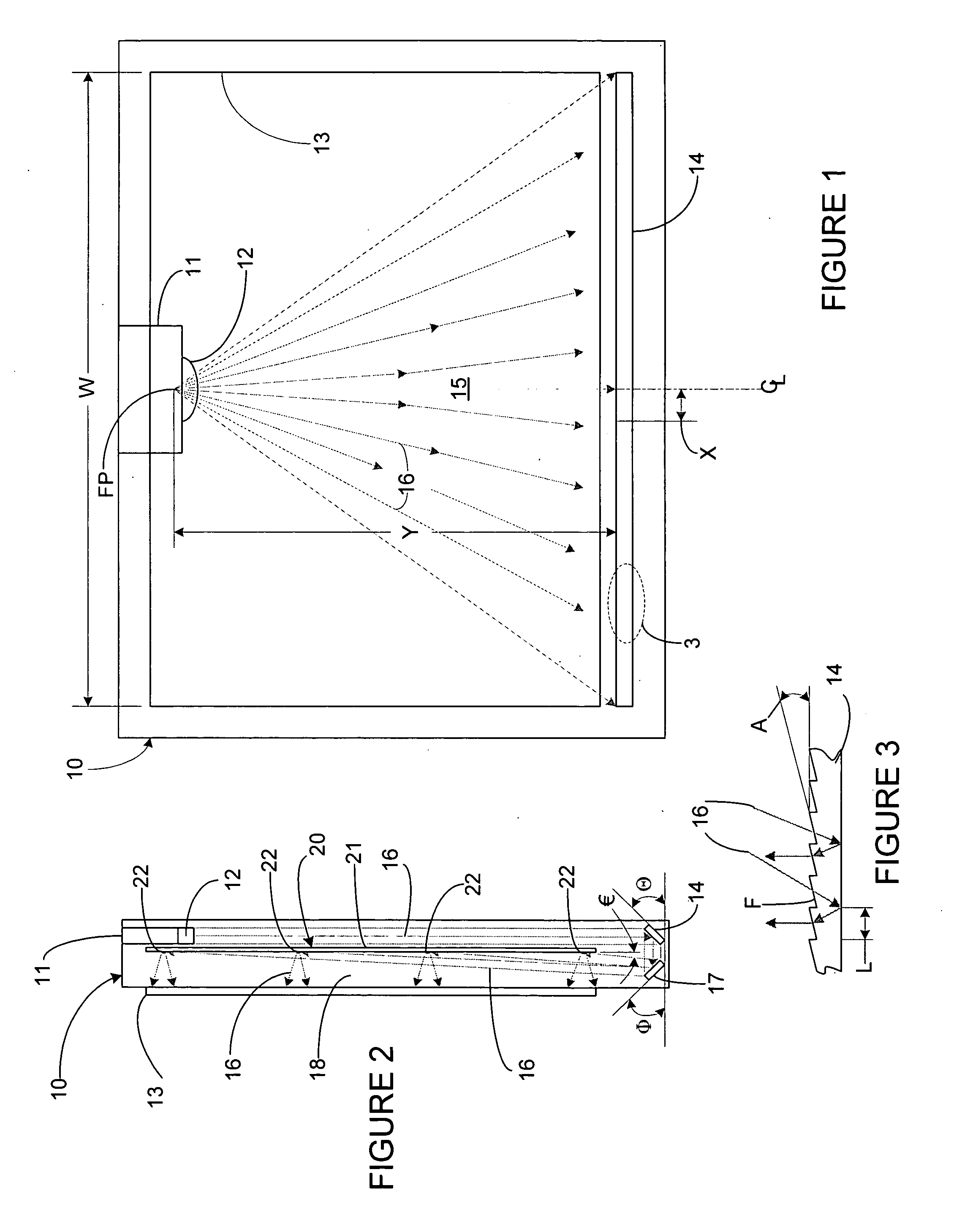
[0012] Each of the additional features and teachings disclosed below can be utilized separately or in conjunction with other features and teachings to provide an improved image projection configuration for a flat projection television set that facilitates the proper folding of optics within a shallow enclosure. Representative examples of the present invention, which examples utilize many of these additional features and teachings both separately and in combination, will now be described in further detail with reference to the attached drawings. This detailed description is merely intended to teach a person of skill in the art further details for practicing preferred aspects of the present teachings and is not intended to limit the scope of the invention. Therefore, combinations of features and steps disclosed in the following detail description may not be necessary to practice the invention in the broadest sense, and are instead taught merely to particularly describe representative ...


PUM


Abstract

A flat projection television comprising an imagine engine mounted adjacent a top of an enclosure and optically coupled to a collimator mirror, a flat mirror, a mirror assembly comprising a plurality of cylindrical mirrors, and a diffuser screen. The image engine includes a cylindrical lens which expands an outgoing image horizontally. The image engine projects the image downward from the top of the enclosure toward the bottom of the enclosure where the horizontally expanding image encounters the collimator mirror which collimates the expanding beam bringing the horizontal lines back into parallel with one another. The collimator mirror also reflects the collimated image towards the front of the enclosure where it encounters the flat mirror oriented to deflect the image upward into the mirror box location of the enclosure at an appropriate angle. As the image is projected from the flat mirror, it encounters the cylindrical mirrors of the mirror assembly which expand each horizontal line of the image to present a fully expanded and complete image on the diffuser screen.

Description

FIELD [0001] The present invention relates generally to projection television sets, and more particularly to a flat or thin projection television configuration. BACKGROUND [0002] Projection television sets were a popular alternative to picture tube television sets, as they provided relatively large viewable screens that could not be efficiently produced using conventional picture tubes. Projection television sets typically include an enclosure with an optical unit, a mirror, and electronic components for receiving and projecting an image onto a screen assembly mounted on the front of the enclosure, and tend to have a relatively deep or thick enclosure. For consumers desirous of thin or relatively flat television sets with large viewable screens, plasma and LCD televisions have become a popular alternative to projection television sets. [0003] In order to make a thin or relatively flat projection television set, the image must be properly folded and projected on to the screen in a re...

Claims


Application Information

Patent Timeline
Patent Type & Authority Applications(United States)
IPC IPC(8): G03B21/22
CPCG03B21/62G03B21/10
Inventor LOWE, JERRY B.
Owner MITSUBISHI ELECTRIC US
Why Eureka
Try Eureka