
Method and apparatus for containing and/or transporting rotor blades

a technology of rotor blades and methods, applied in the field of transportation containers, can solve the problems of affecting the performance of the blad

Inactive Publication Date: 2007-08-02
GENERAL ELECTRIC CO
View PDF19 Cites 69 Cited by
  • Summary
  • Abstract
  • Description
  • Claims
  • Application Information

AI Technical Summary

Benefits of technology

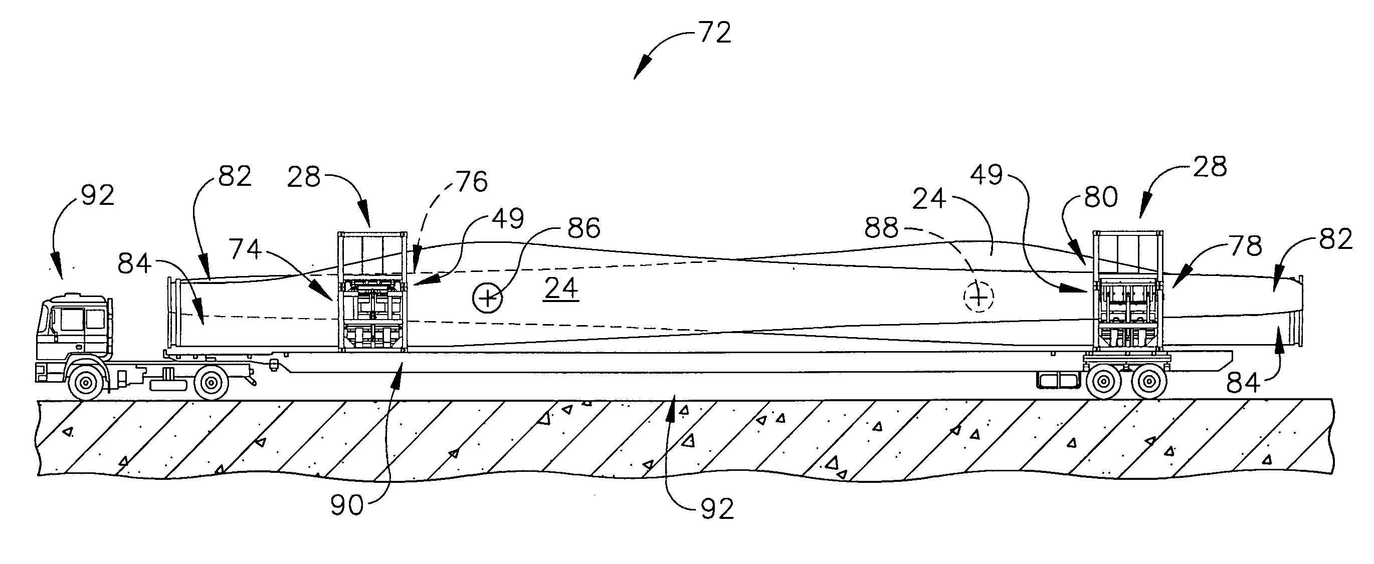
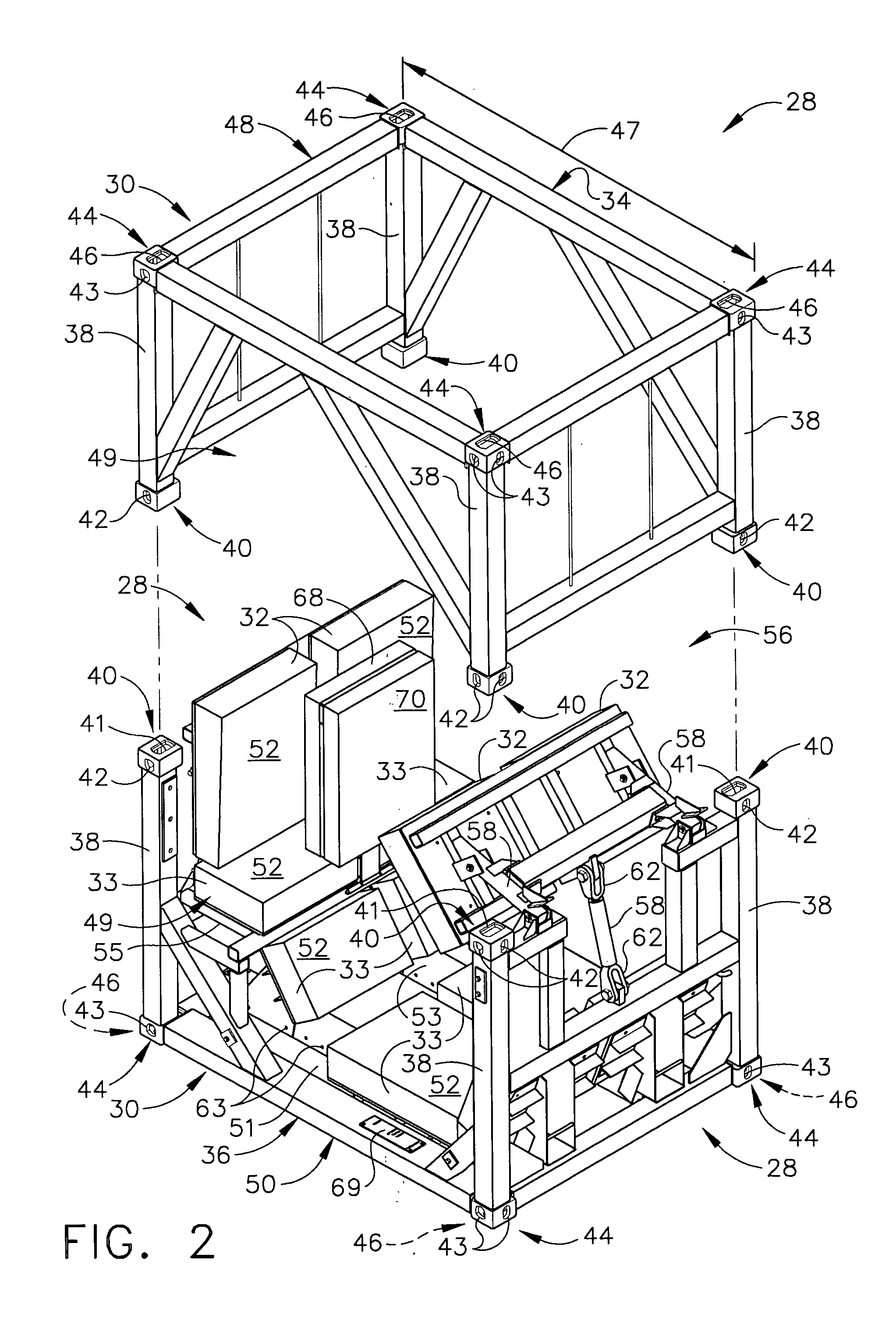
[0006] In another aspect, a method is provided for at least one of supporting and transporting a rotor blade using a frame having a space defined between at least two portions thereof and a cushion selectively positionable relative to the frame in at least two different positions wherein the cushion is coupled to the frame. The method includes receiving a portion of the rotor blade within the frame space, positioning the cushion such that the cushion engages the rotor blade portion to facilitate at least one of supporting the rotor blade portion and containing the rotor blade portion, and transporting the frame to thereby transport the rotor blade.

Problems solved by technology

Because of their size and / or fragility, some known large rotor blades may be damaged during transportation from where the rotor blades are manufactured to where the rotor blades are used.
For example, some known rotor blades may be damaged during loading into and / or unloading from at least some known transportation containers.
Such damage may degrade performance of the blade.
Accordingly, at least some known transportation containers are sized to fit the largest blade, which may increase a weight and overall size of transporting smaller blades.
However, providing different containers may increase a cost and / or difficulty of transporting rotor blades, for example because of possible logistical difficulties of providing that containers of the proper size are available for each shipment and / or additional manufacturing and / or design processes.
However, some modes of transportation may have restrictions on large loads, for example height and / or width limits thereof.
However, such limits may increase a difficulty of transporting more than one rotor blade in a single container, which may increase a cost of transporting some known rotor blades and / or increase an impractability of transporting more than one blade in a single container.

Method used


Image

  • Method and apparatus for containing and/or transporting rotor blades
  • Method and apparatus for containing and/or transporting rotor blades
  • Method and apparatus for containing and/or transporting rotor blades

Examples


Embodiment Construction

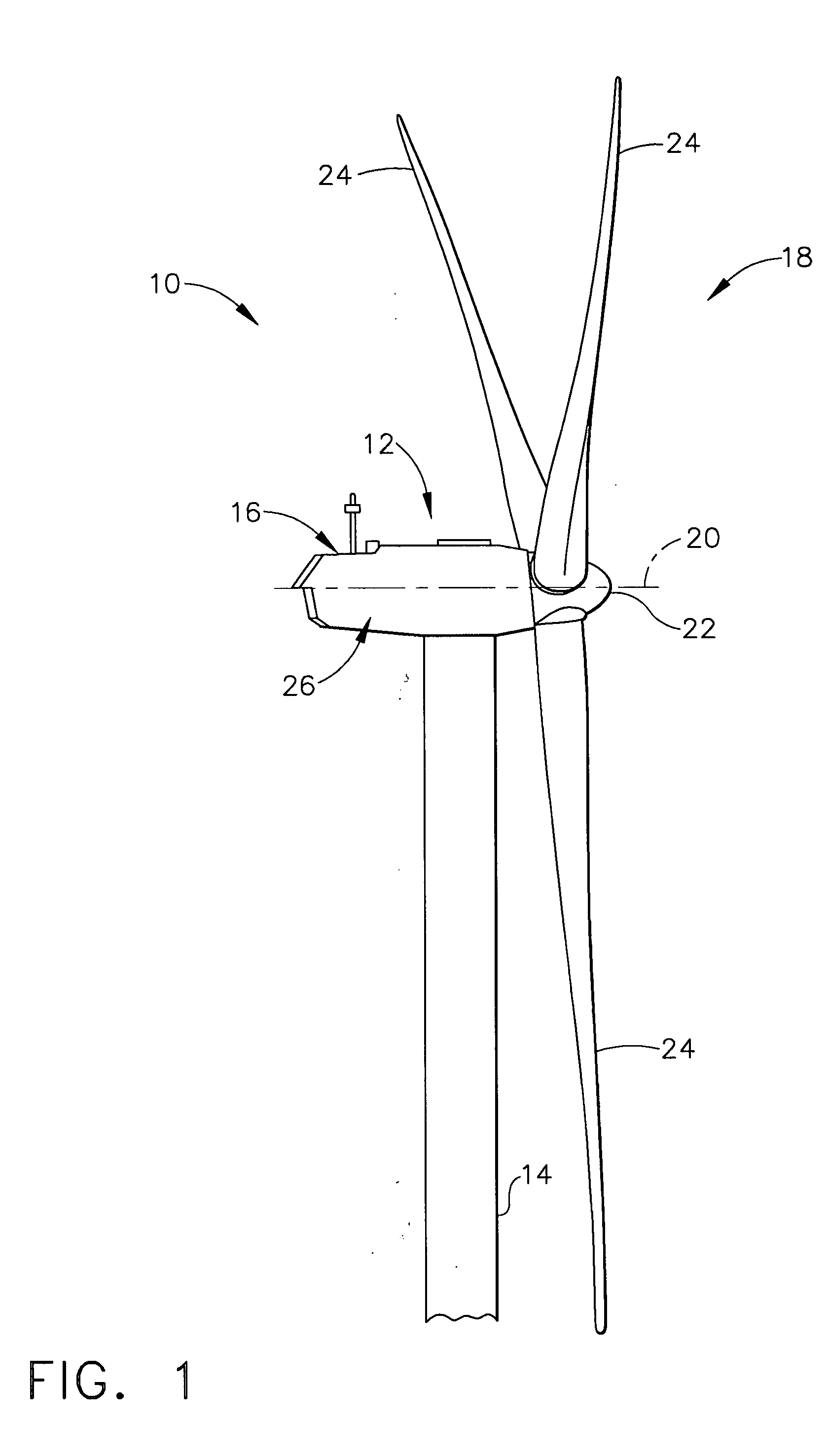
[0016] As used herein, the term “blade” is intended to be representative of any device that provides reactive force when in motion relative to a surrounding fluid. As used herein, the term “wind turbine” is intended to be representative of any device that generates rotational energy from wind energy, and more specifically, converts kinetic energy of wind into mechanical energy. As used herein, the term “wind generator” is intended to be representative of any wind turbine that generates electrical power from rotational energy generated from wind energy, and more specifically, converts mechanical energy converted from kinetic energy of wind to electrical power. As used herein, the term “windmill” is intended to be representative of any wind turbine that uses rotational energy generated from wind energy, and more specifically mechanical energy converted from kinetic energy of wind, for a predetermined purpose other than generating electrical power, such as, but not limited to, pumping ...


PUM


Abstract

A fixture for at least one of supporting and transporting a load. The fixture includes a frame having a space defined between at least two portions of the frame. The space is configured to receive a portion of the load. The fixture also includes at least one cushion selectively positionable relative to the frame in at least two different positions wherein the at least one cushion is coupled to the frame to facilitate at least one of containing and supporting at least a portion of the load.

Description

BACKGROUND OF THE INVENTION [0001] This invention relates generally to transportation containers, and more specifically to methods and apparatus for containing and / or transporting rotor blades. [0002] Some known rotor blades, such as, but not limited to, wind turbine rotor blades used to generate electrical power from wind, can be rather large (e.g., some exceeding 160 feet in length and 12 feet in width). Because of their size and / or fragility, some known large rotor blades may be damaged during transportation from where the rotor blades are manufactured to where the rotor blades are used. For example, some known rotor blades may be damaged during loading into and / or unloading from at least some known transportation containers. Such damage may degrade performance of the blade. [0003] Rotor blades may come in a variety of different sizes and shapes. Accordingly, at least some known transportation containers are sized to fit the largest blade, which may increase a weight and overall ...

Claims


Application Information

Patent Timeline
IPC IPC(8): B60P3/40
CPCB60P3/40Y02E10/72F03D1/005B65D88/121F03D13/40
Inventor KOOTSTRA, DIRK-JANRIXTEN, ANDRE
Owner GENERAL ELECTRIC CO
Learn More