Gear pump with ripple chamber for low noise and pressure ripples

a technology of pump ripple and ripple chamber, which is applied in the direction of liquid fuel engines, machines/engines, rotary piston liquid engines, etc., can solve the problems of vibration and/or noise, fluid to be trapped in a region,

Inactive Publication Date: 2007-08-02
PARKER HANNIFIN CORP
View PDF22 Cites 24 Cited by
  • Summary
  • Abstract
  • Description
  • Claims
  • Application Information

AI Technical Summary

Benefits of technology

[0007] Accordingly, the invention provides a gear pump comprising a gear chamber having opposite side walls; a pair of gears disposed within the gear chamber with teeth thereof meshed with one another, the meshed teeth forming a trap region in which fluid becomes entrapped during rotation of the gears; inlet and outlet chambers on opposite sides of the meshed teeth of the gears and separated from one another by the meshed teeth of the gears; a ripple chamber; and a first passage connecting the ripple chamber to the trap region, whereby the trapped high pressure fluid will flow from the trap region to the ripple chamber to dampen the otherwise generated high pressure pulse.

Problems solved by technology

During rotation of the gears, the nature of the teeth can cause fluid to be trapped in a region defined between the gears and compressed.
When the high pressure trapped fluid is released to outlet chamber, a high pressure pulse, or ripple, is produced in the pump output, and this can cause vibration and / or noise.

Method used


Image

  • Gear pump with ripple chamber for low noise and pressure ripples
  • Gear pump with ripple chamber for low noise and pressure ripples
  • Gear pump with ripple chamber for low noise and pressure ripples

Examples


Embodiment Construction

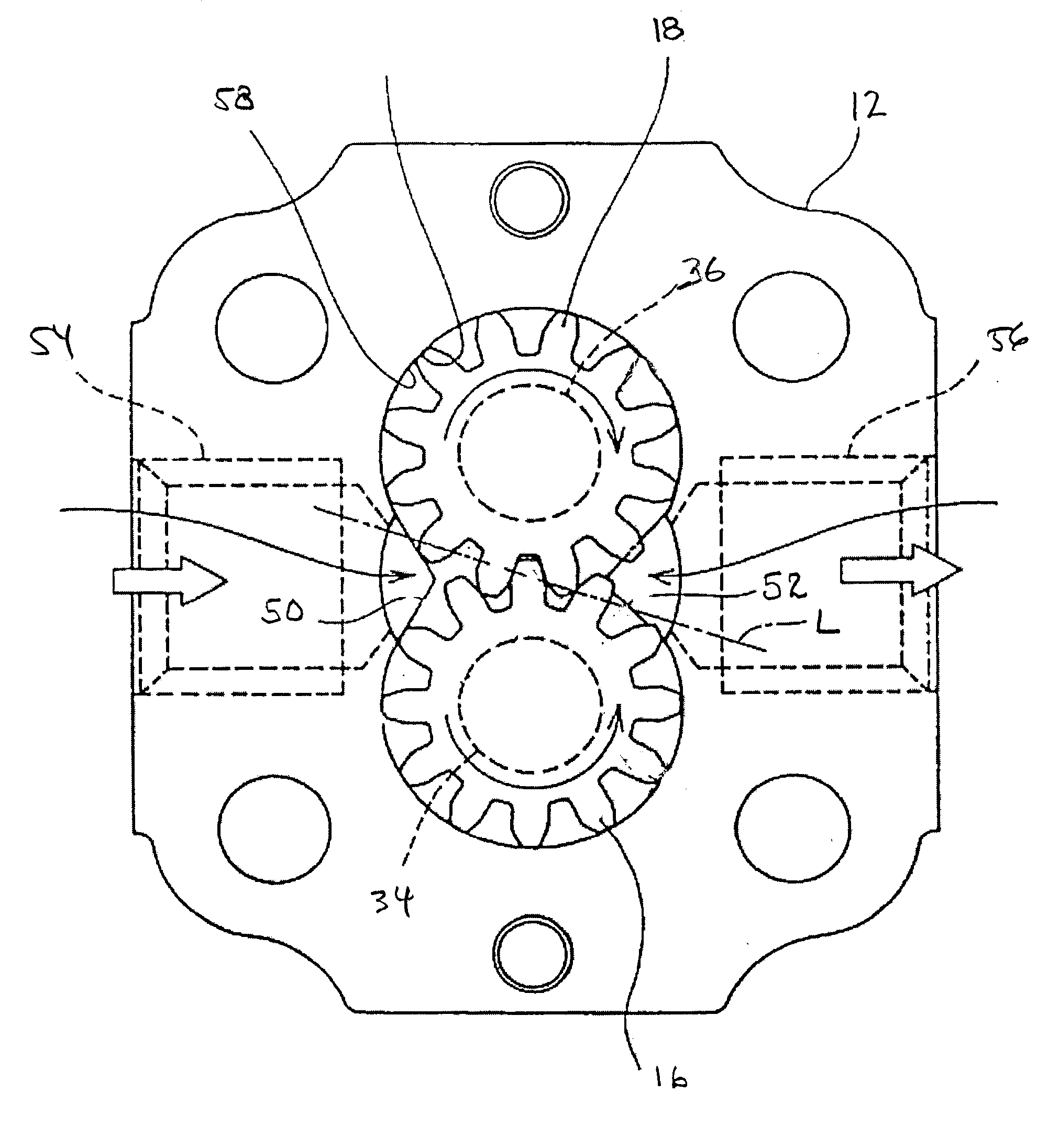
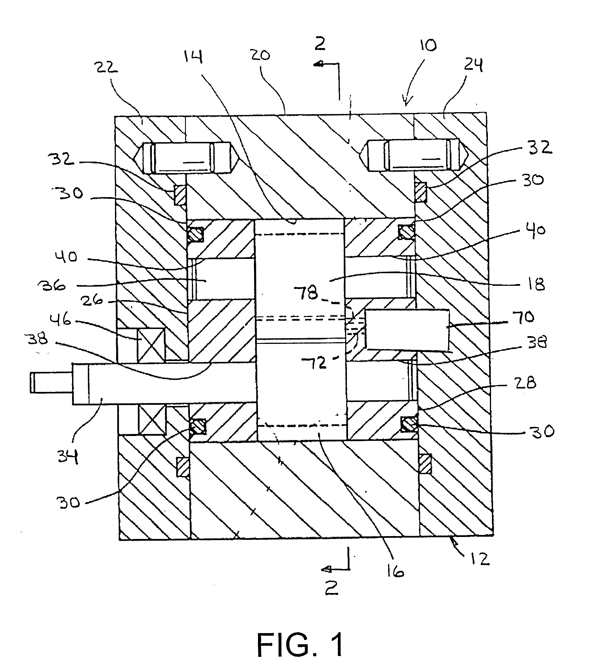
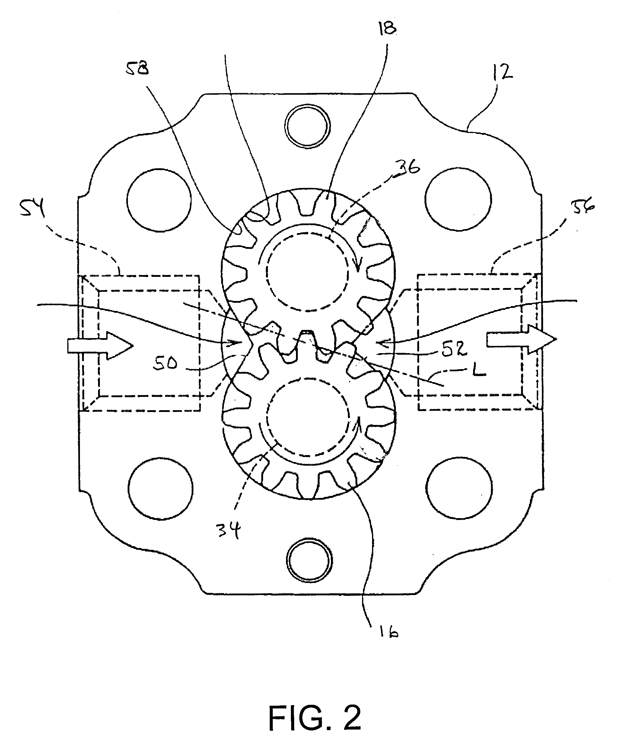
[0015] Referring now to the drawings in detail and initially to FIGS. 1 and 2, an exemplary gear pump according to the present invention is designated generally by reference numeral 1. The gear pump 10 has a housing 12 (also sometimes referred to as a casing) including an interior gear chamber 14 containing a pair of gears 16 and 18. In the illustrated embodiment, the housing includes a central body 20 in which the chamber 14 is formed and opposite end plates 22 and 24. The ends of the chamber 14 containing the gears 16 and 18 are closed by thrust plates 26 and 28 located inwardly of the end plates 22 and 24. As is typical of some conventional gear pumps, the thrust plates may be formed by the housing end plates, and still other configurations may be used as may be desired. As shown, seals 30 may be provided between the thrust plates and the corresponding cover plates. In addition, seals 32 may be provided between the end plates and the gear chamber body as shown.

[0016] A pair of g...


PUM


Abstract

A gear pump comprising a gear chamber having opposite side walls; a pair of gears disposed within the gear chamber with teeth thereof meshed with one another, the meshed teeth forming a trap region in which fluid becomes entrapped during rotation of the gears; inlet and outlet chambers on opposite sides of the meshed teeth of the gears and separated from one another by the meshed teeth of the gears; a ripple chamber; and a first passage connecting the ripple chamber to the trap region, whereby the trapped high pressure fluid will flow from the trap region to the ripple chamber to dampen the otherwise generated high pressure pulse.

Description

RELATED APPLICATIONS [0001] This application claims the benefit of U.S. Provisional Application No. 60 / 739,050 filed Nov. 22, 2005, which is hereby incorporated herein by reference.FIELD OF THE INVENTION [0002] The present invention relates to gear pumps and more particularly to gear pumps having low noise and pump ripples. BACKGROUND OF THE INVENTION [0003] Gear pumps generally comprise a gear chamber defined between a pair of side plates. A pair of meshed gears are accommodated in the gear chamber and supported on shafts for rotation. One shaft is rotatably driven to rotate one gear, which in turn rotates the other gear through interaction of the meshed gear teeth. A fluid inlet chamber and a fluid outlet chamber are provided on opposite sides of the meshed teeth of the gears, such that upon rotation of the gears, fluid is sucked from the inlet chamber and discharged at a higher pressure through the outlet chamber. [0004] During rotation of the gears, the nature of the teeth can c...

Claims


Application Information

Patent Timeline
Patent Type & Authority Applications(United States)
IPC IPC(8): F01C1/18F01C1/24F03C2/00
CPCF04C2/18F04C2/088
Inventor ZHU, JONATHANJONES, JOHNKOVACH, JOSEPHJOHNSON, CHRIS
Owner PARKER HANNIFIN CORP
Why Eureka
Try Eureka