High-Stress Seals for Injection Molding Machines

a technology of injection molding machine and high-stress seal, which is applied in the field of high-stress seals, can solve the problems of plastic resin tending to force itself, ooze out, and high cost of manufacture of such precision seals, and achieve the effect of less cost and higher pressure level

Inactive Publication Date: 2007-08-02
INCOE CORP
View PDF2 Cites 6 Cited by
  • Summary
  • Abstract
  • Description
  • Claims
  • Application Information

AI Technical Summary

Benefits of technology

[0006]The invention is based on the need to develop high-stress seals for injection molding melt delivery systems, wh...

Problems solved by technology

They secure the gap between the two coplanar contact surfaces; however, under very high pressure, the plastic resin tends to force itself into the space between the seal and the ...

Method used


Image

  • High-Stress Seals for Injection Molding Machines
  • High-Stress Seals for Injection Molding Machines
  • High-Stress Seals for Injection Molding Machines

Examples


Embodiment Construction

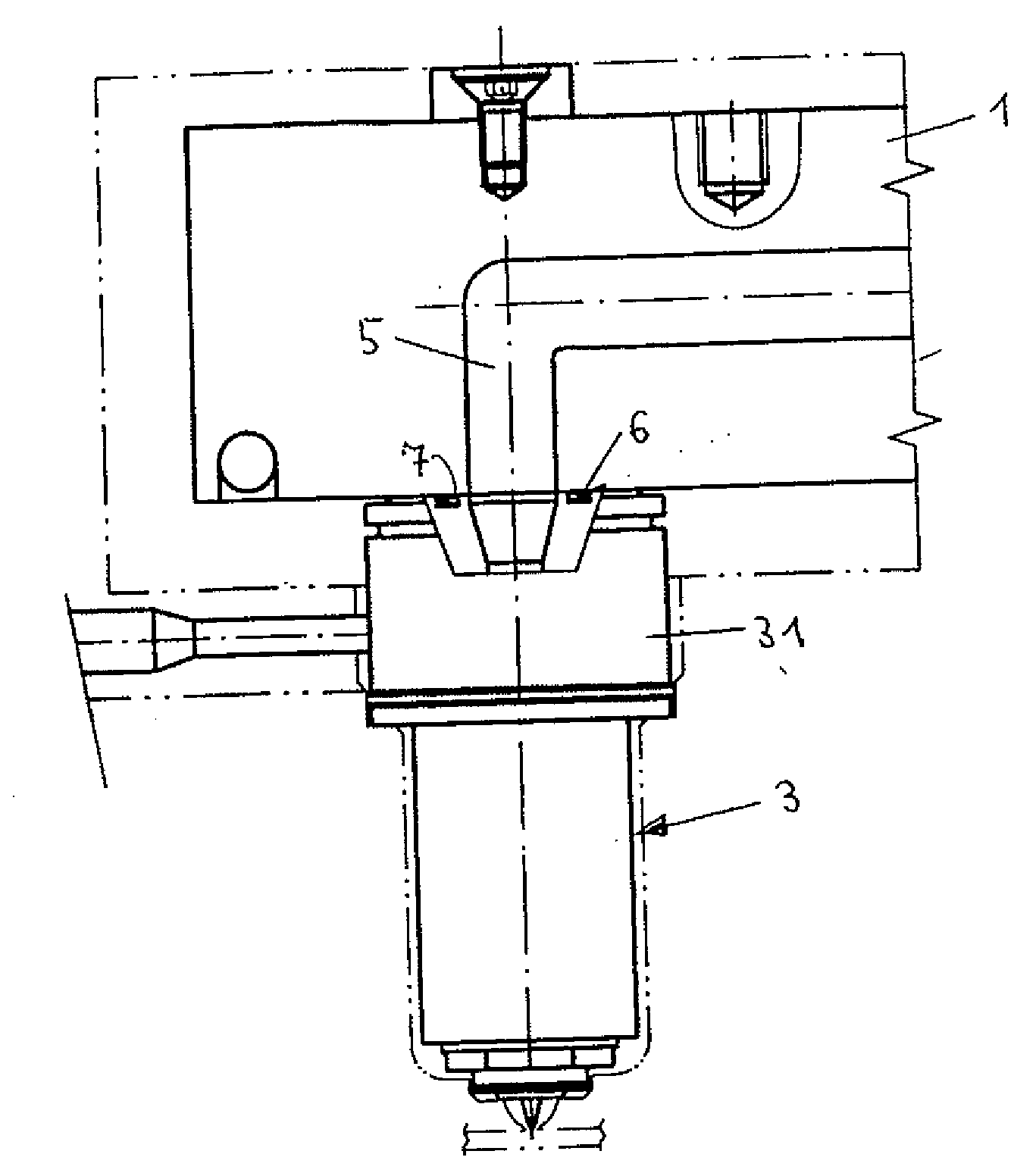
[0017]FIG. 1 shows the connection of a nozzle (3) to a partially depicted manifold (1) through whose flow channel (5) plastic resin is supplied by an injection machine.

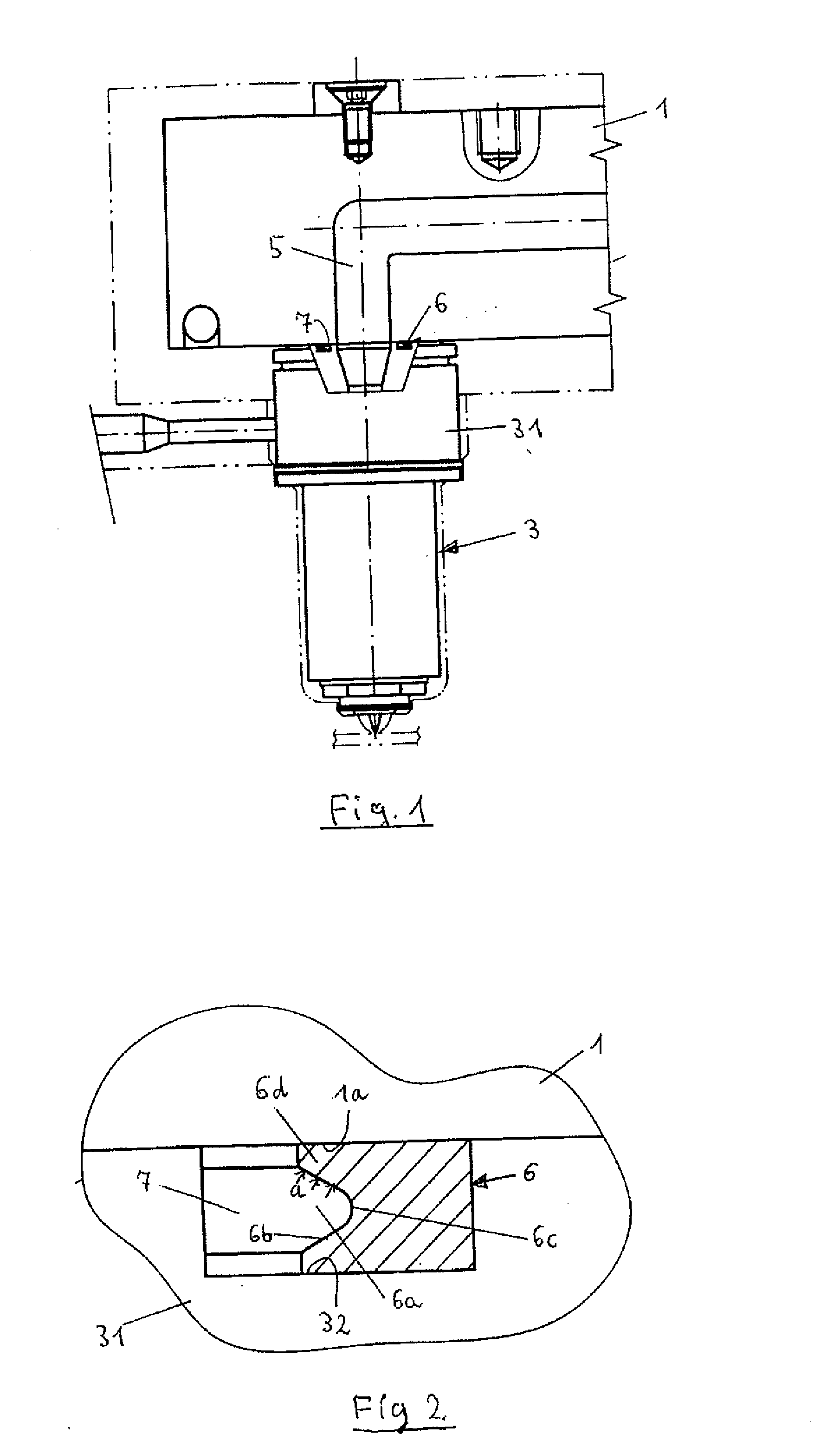
[0018]Compression due to thermal expansion is pressing the nozzle (3) and the manifold (1) firmly against one another. A seal is necessary at the transition point between the manifold (1) and the nozzle (3) between two coplanar surfaces. The seal (6) lies in a radial groove (7) in the rear (upper) end face of the nozzle head (31). It is a high-stress seal according to the invention, whose construction can be seen more precisely in FIG. 2: The seal (6) has a radial groove (6a) on its side closest to the flow channel. In the implementation example shown, this groove has tapered sides (6b) and a rounded bottom (6c). Thus, its profile resembles a triangle in which the bottom (6c) that forms the peak is very rounded. If the highly pressurized plastic resin is forced into the free space of the groove (7), it presses onto th...


PUM

PropertyMeasurementUnit
Fractionaaaaaaaaaa
Pressureaaaaaaaaaa
Temperatureaaaaaaaaaa

Abstract

A high-stress seal for injection molding machines, intended for sealing the gap between the injector nozzle and the injector rail of the tool. The seal in the ingate area is designed in a dome shape with an opening in the top of the dome for flux to enter. Correspondingly, the injector nozzles and the opposing wall of the injector rail of the tool have a dome-shaped design and are spatially adapted to the seal. This construction provides the seal with very dense, firm placement when the injector is pressed into the tool recess, and flux under high pressure cannot dislodge it.

Description

BACKGROUND OF THE INVENTION[0001]The present invention relates generally to high-stress seals for injection molding melt delivery systems.[0002]During injection, plastic resin is forced from an injection machine, directly or through a manifold, into a nozzle, and from this into a mold cavity. Injection machines, manifolds, nozzles and molds are separate parts, and at the melt channel transition points from one part to another, an outside seal must be provided. Great demands are placed on these seals, because, due to its high temperatures, the plastic resin flowing through the melt channels has a low viscosity comparable to water, and the molten material is under high pressure.[0003]Between the injection machine and the manifold, as between the manifold and nozzle, gasket seals in the form of O-rings are generally used, which are placed in a groove in one of the two coplanar surfaces. They secure the gap between the two coplanar contact surfaces; however, under very high pressure, th...

Claims


Application Information

Patent Timeline
IPC IPC(8): B29C45/20
CPCB29C45/27B29C45/2725B29C45/278F16J15/3236B29C2045/2762B29C2045/2767B29C2045/2761
Inventor GOINSKI, MICHAEL
Owner INCOE CORP
Why Eureka
Try Eureka