
Methods Utilizing Steganography

a technology of steganography and steganography, applied in the field of computer systems, can solve the problems of raising the spectre of an orwellian “big brother”, a rampant problem of counterfeiting, and a lack of steganography, so as to improve the capabilities of systems, the effect of rapid technology advancement, and increasing availability and affordability

Inactive Publication Date: 2007-08-02
DIGIMARC CORP
View PDF99 Cites 56 Cited by
  • Summary
  • Abstract
  • Description
  • Claims
  • Application Information

AI Technical Summary

Benefits of technology

[0009] This trend is attributed to rapid improvements in technology, and the ever-increasing availability and affordability of scanners, high-resolution inkjet and other output devices, and computer systems. Digital counterfeiting is likely to continue to increase as the capabilities of systems and devices continue to improve, and as these capabilities become more readily understood by the criminal element.

Problems solved by technology

Today, counterfeiting is a rampant problem practiced by thousands of criminals using ubiquitous computer equipment.
If such a photocopier is presented with a banknote for duplication, copying is disabled or impaired.
Unbounded use of such covert marking techniques can raise the spectre of an Orwellian “Big Brother.”
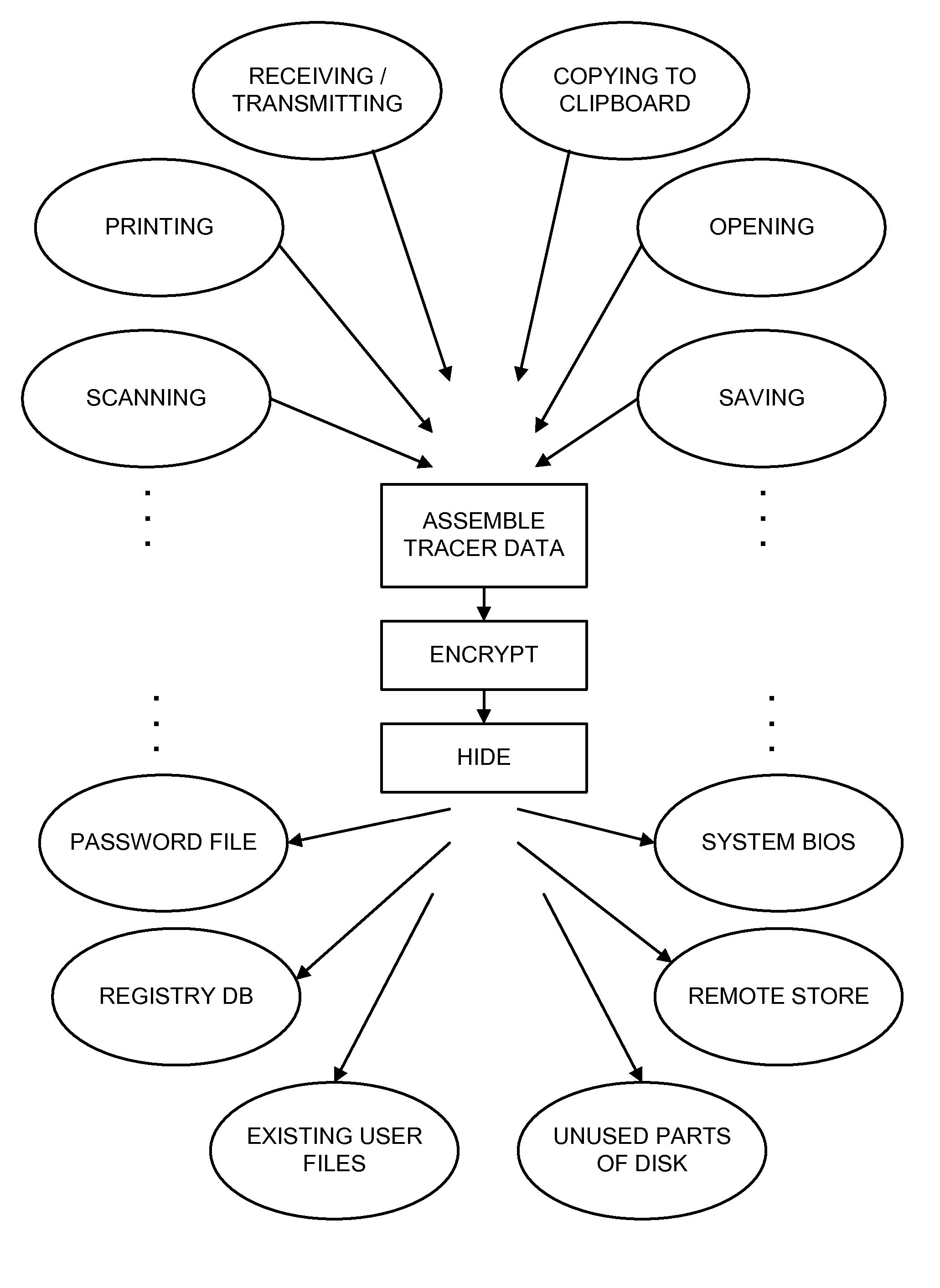
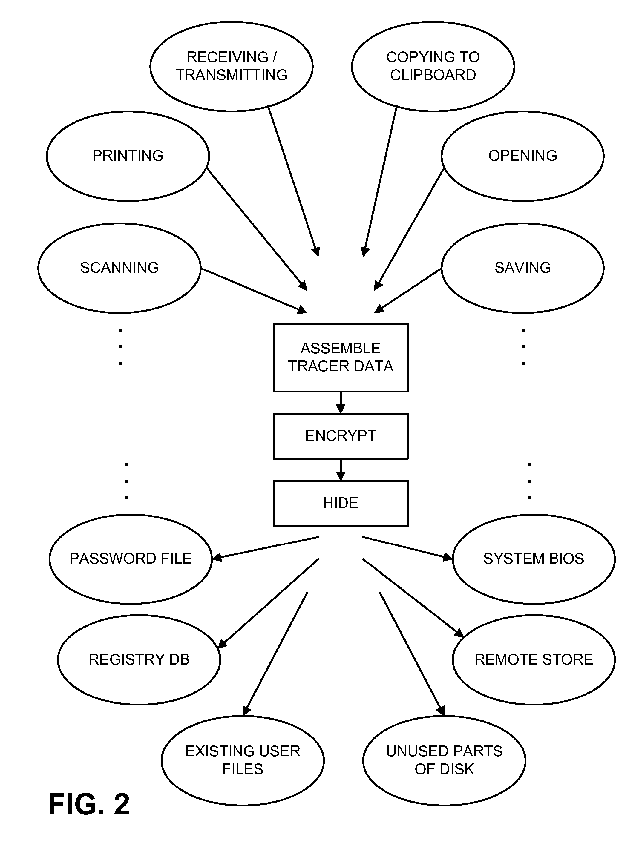
However, instead of rotely incorporating such data into all printed output, it is secretly stored in the counterfeiter's computer.

Method used


Image

  • Methods Utilizing Steganography
  • Methods Utilizing Steganography
  • Methods Utilizing Steganography

Examples


Embodiment Construction

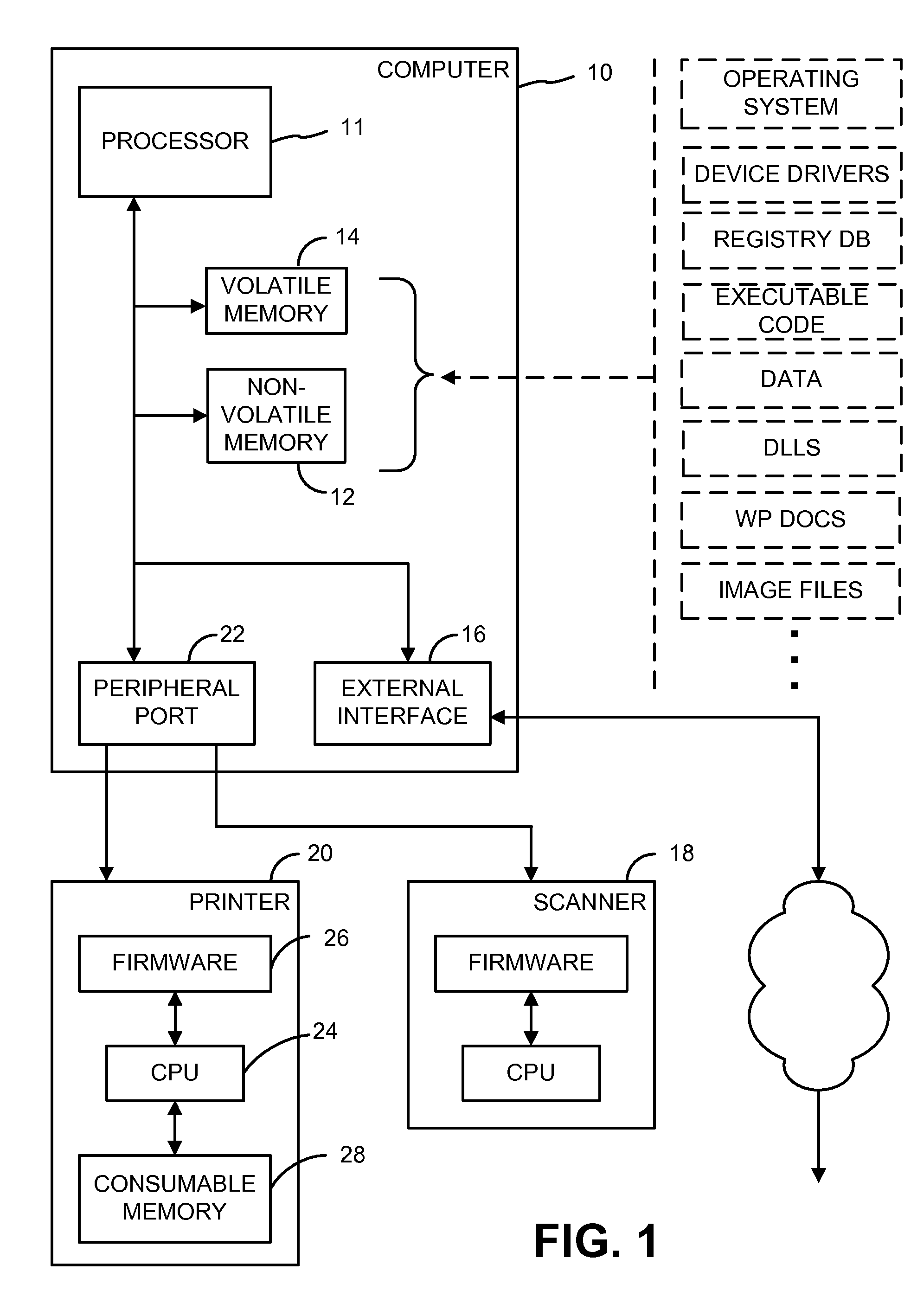
[0019] Referring to FIG. 1, a computer system 10 employed in one embodiment of the present invention includes a processor 11, a non-volatile store 12, volatile memory 14, an external interface 16, and various peripherals (e.g. a scanner 18, a printer 20, etc.).

[0020] The processor 11 typically comprises a CPU, such as one of the microprocessors available from Intel, Sun, AMD, Cyrix, Motorola, MIPS, etc. Alternatively, the processor can take other forms, including hardwired logic circuitry, programmable logic (e.g. FPGAs), or yet-to-be-devised processing arrangements.

[0021] The non-volatile store 12 typically comprises a magnetic disk, but can also include other writeable media, including optical disks, flash memory, EEPROMS, ROMBIOS, etc. The non-volatile store can be physically located with the processor 11 (e.g. hard disk, CMOS memory with system setup data, etc), and / or can be remote (e.g. a networked drive, storage accessible over the Internet, etc.).

[0022] The volatile memor...


PUM


Abstract

The present invention relates generally to steganography, digital watermarking and data hiding. In one embodiment a method is provided including: processing data representing content; analyzing the data to determine whether a plural-bit identifier is steganographically encoded therein, the plural-bit identifier encoded in the data through modifications to the data, the modifications steganographically hiding the presence of the plural-bit identifier; and upon detection of the plural-bit identifier, redundantly carrying out an action while attempting to conceal the action from one or more users of the content. Of course, other embodiments are described and claimed as well.

Description

RELATED APPLICATION DATA [0001] This application is a continuation-in-part of U.S. patent application Ser. No. 10 / 639,598, filed Aug. 11, 2003 (published as US 2006-0028689 A1). [0002] The U.S. patent application Ser. No. 10 / 639,598 is a continuation-in-part of U.S. patent application Ser. No. 10 / 367,092, filed Feb. 13, 2003 (now U.S. Pat. No. 7,113,615), which is a continuation-in-part of U.S. patent application Ser. No. 09 / 185,380, filed Nov. 3, 1998 (now U.S. Pat. No. 6,549,638). [0003] The U.S. patent application Ser. No. 10 / 639,598 is also a continuation-in-part of U.S. patent application Ser. No. 09 / 465,418, filed Dec. 16, 1999 (abandoned), which claims the benefit of U.S. Provisional Patent Application No. 60 / 112,955, filed Dec. 18, 1998. [0004] The above U.S. patent documents are hereby incorporated by reference.FIELD OF THE INVENTION [0005] The present invention relates to computer systems, and more particularly relates to techniques for establishing persistent evidence of ...

Claims


Application Information

Patent Timeline
IPC IPC(8): H04L9/00
CPCG06F21/16H04N2201/327H04N1/32203
Inventor CARR, J. SCOTTDAVIS, BRUCE L.RHOADS, GEOFFREY B.
Owner DIGIMARC CORP
Learn More