Punch press alignment instrument

a technology of alignment instruments and punch presses, applied in the field of punching and die art, can solve the problems of no indication, cumbersome operation of devices, and inability to indicate, and achieve the alignment tolerances that are not as good as are sometimes required

Active Publication Date: 2007-08-09
MATE PRECISION TOOLING
View PDF17 Cites 25 Cited by
  • Summary
  • Abstract
  • Description
  • Claims
  • Application Information

AI Technical Summary

Benefits of technology

[0006] Another general object is to provide an improved alignment instrument that will align a punch and a die in three ways simultaneously; horizontally on perpe

Problems solved by technology

The device was cumbersome to operate and there was no means of indicating when the upper and lower parts of the device were in alignment.
Alignment tolerances were also not as good as are sometimes r

Method used


Image

  • Punch press alignment instrument
  • Punch press alignment instrument
  • Punch press alignment instrument

Examples


Embodiment Construction

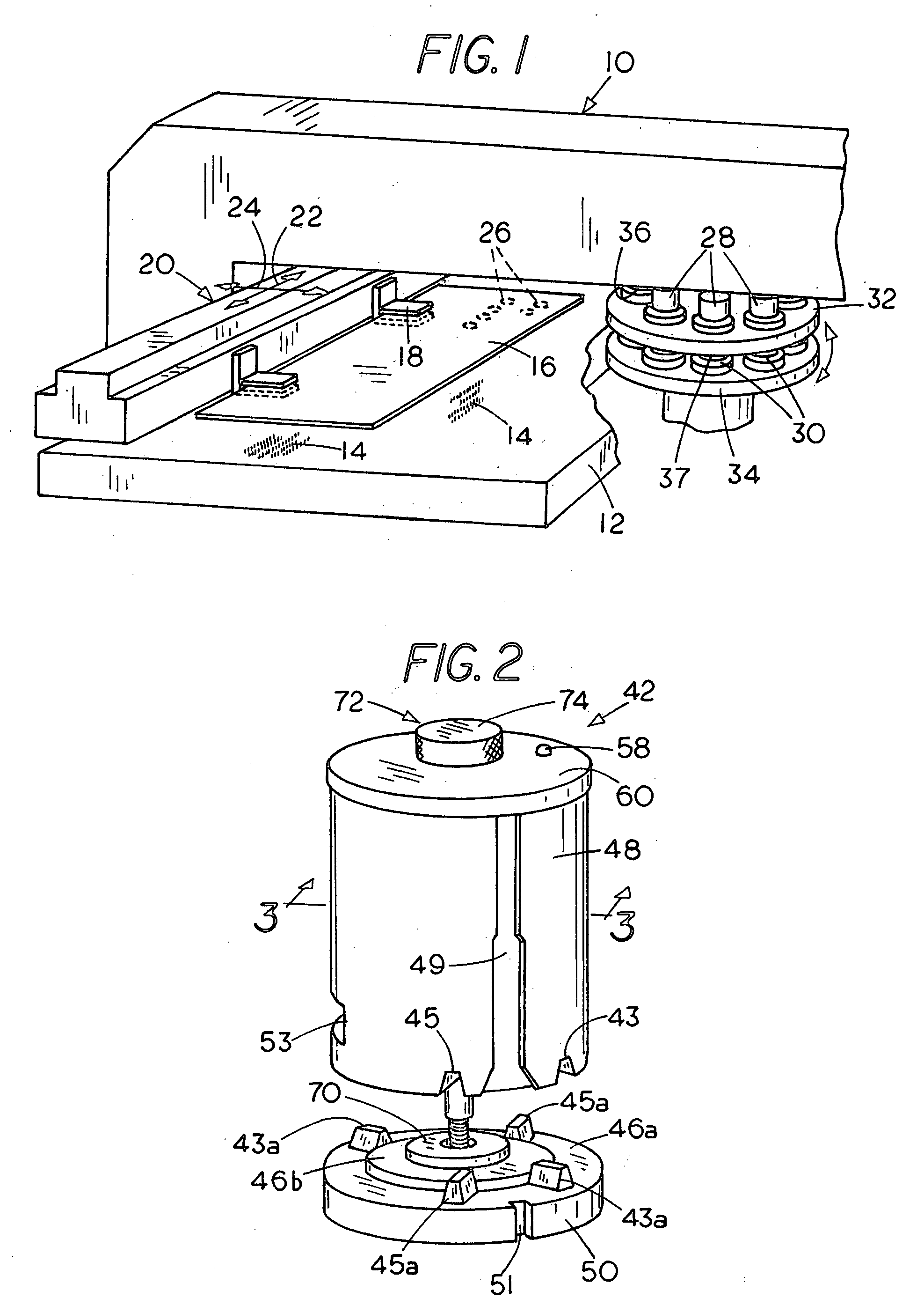
[0029] The invention can be employed in several different kinds of punch presses one of which is illustrated by way of example in FIG. 1. The punch press indicated generally by the numeral 10 includes a fixed base 12 that may be provided with vertically extending fibers 14 only a few of which are shown for supporting workpiece 16 that is securely held by a pair of clamps 18 which are in turn connected to a positioning rail 20 that is moved rapidly during operation to a series of programmed positions along horizontal x and y axes 22 and 24 under the automatic control of a computer (not shown) to punch a series of openings 26 in the workpiece 16 or otherwise form the workpiece each time the workpiece is brought into the proper position between a punch 28 and cooperating die 30. The punches 28 are distributed circumferentially on a circular punch turret 32 and the dies 30 in turn are each supported on a lower turret 34 in alignment below one of the punches. During operation, the turret...


PUM

PropertyMeasurementUnit
Displacementaaaaaaaaaa

Abstract

A punch press alignment instrument has upper and lower cylindrical components that are associated for vertical displacement relative to one another. Both components have outer tool holder engaging surfaces which are to be aligned with one another so as to in turn align the tool holders of the punch press when the upper and lower components themselves are in alignment. Alignment elements, e.g., ridges and grooves provided on mating surfaces of the components confronting each other are brought into contact with one another to move the components of the instrument into mutual alignment. An alignment control member, e.g., a screw is preferably provided for progressively bringing the upper and lower components toward one another and an indicator such as a lamp, a dial indicator or an audible indicator is provided for denoting the spacing between the upper and lower components to thereby confirm the alignment of the tool holders. A releasable element is used to temporarily hold the upper and lower components apart when they are spaced laterally from one another or for any reason are not capable of being placed in alignment.

Description

[0001] This application is a continuation in part of application Ser. No. 11 / 125,988 filed May 9, 2005 entitled PUNCH PRESS ALIGNMENT INSTRUMENT which is incorporated herein by reference.FIELD OF THE INVENTION [0002] This invention relates to the punch and die art and more particularly to an alignment instrument for a punch press. BACKGROUND OF THE INVENTION [0003] In many standard punch presses, a punch element is carried on an upper turret in alignment over a die that is mounted on a lower turret. The punch and die are both held in circular tool holders. Before the press can be operated, the tool holders must be placed in vertical alignment with one another so that the punch and die are in turn in alignment during operation. An alignment tool previously used by the assignee of the present invention included upper and lower parts in which the upper part was provided with a pair of laterally spaced apart downwardly extending cylindrical pins that were placed in corresponding cylindr...

Claims


Application Information

Patent Timeline
IPC IPC(8): G01D21/00
CPCB21D28/125Y10T29/49897B21D28/04Y10T83/9423
Inventor MORGAN, CHRISTOPHER D.
Owner MATE PRECISION TOOLING
Why Eureka
Try Eureka