Parts for vehicles and line heater unit for snow-melting structure part thereof

a technology for heating units and vehicles, applied in electric/magnetic/electromagnetic heating, lighting and heating apparatus, transportation and packaging, etc., can solve the problems of snow, ice or fogging adhesion to front lenses to melt or be removed, wrinkles or distortions on base films, and higher manufacturing costs

Inactive Publication Date: 2007-08-09
ICHIKOH IND LTD +1
View PDF29 Cites 34 Cited by
  • Summary
  • Abstract
  • Description
  • Claims
  • Application Information

AI Technical Summary

Problems solved by technology

Then, the conductive foil pattern generates heat, which causes snow, ice, or fogging adhered to a front lens to melt or to be removed.
However, in the conventional part for vehicles, a wiring board heater (a conductive foil pattern is printed -on a base film) is joint-molded in a front lens through insert molding so that it is necessary to use a specific mold, leading to higher manufacturing costs.
For this reason, when a wiring board heater is adhered to a front lens in conventional parts for vehicles, a wrinkle or distortion occurs on a base film.
As a result, a wrinkle or distortion may occur in a conductive foil pattern printed on the base film.
Similar problem exists in parts that need a snow-melting structure other than the front lens, for example, a part in a window glass, mirror, or a wiper blade of the vehicle.

Method used


Image

  • Parts for vehicles and line heater unit for snow-melting structure part thereof
  • Parts for vehicles and line heater unit for snow-melting structure part thereof
  • Parts for vehicles and line heater unit for snow-melting structure part thereof

Examples


first embodiment

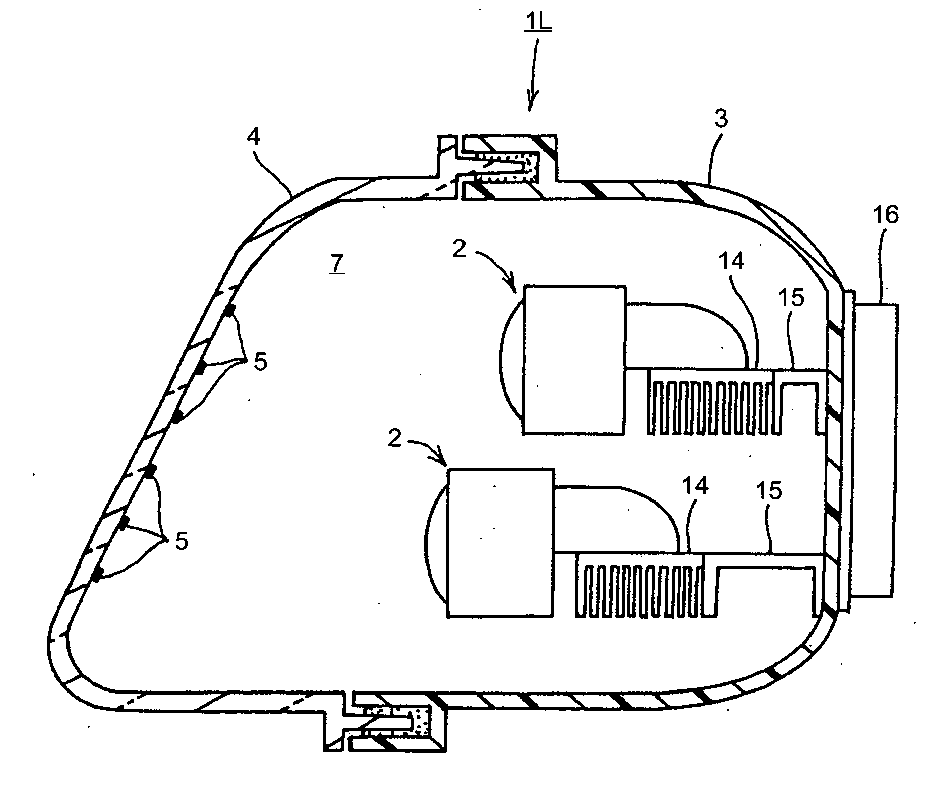
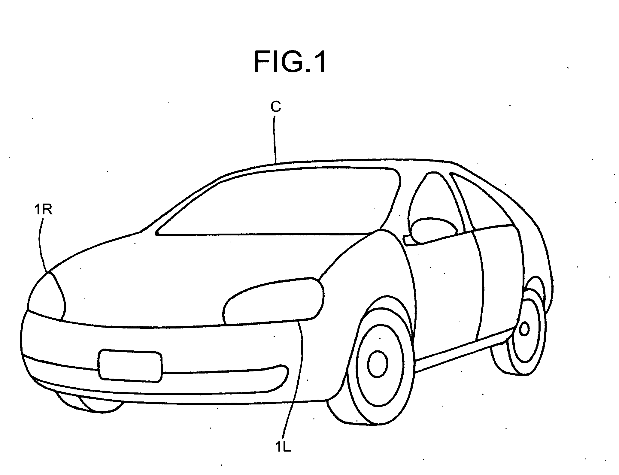
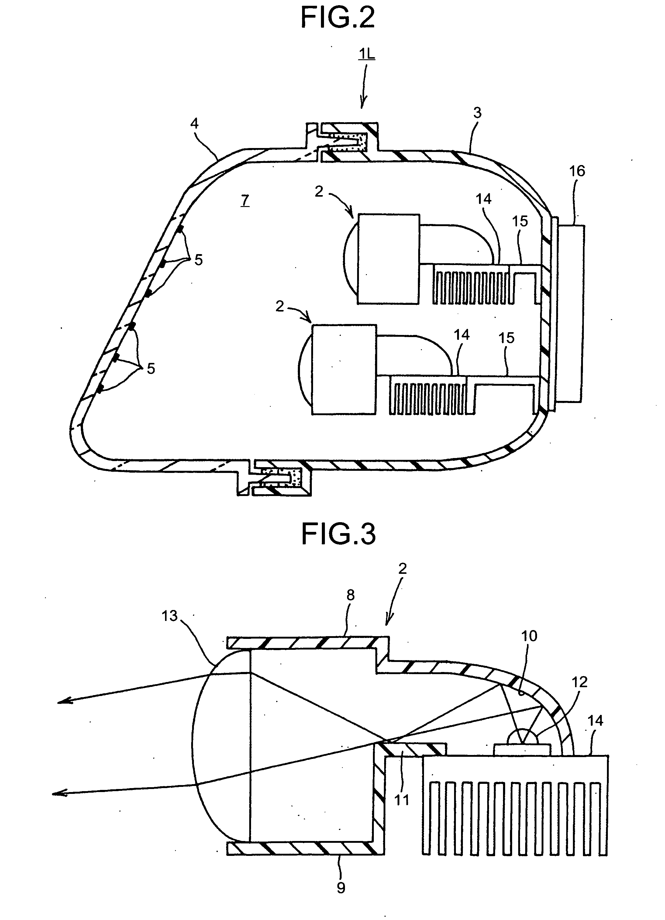
[0036] FIGS. 1 to 10 are schematics of parts for vehicles and a line heater unit according to the present invention. Configurations of the parts for vehicles and the line heater unit are explained below. The parts for vehicles are head lamps 1L, 1R that emit light beams in a predetermined light distribution, for example, a low-beam distribution pattern. The head lamps 1L, 1R are mounted on both of right and left front sides of the vehicle C as shown in FIG. 1. The head lamp 1L on the left side is explained below. The head lamp 1R on the right side is substantially reversed left to right with respect to the head lamp 1L in configuration so that the explanation of head lamp 1R is omitted.

[0037] The head lamp 1L, as shown in FIGS. 2 and 4, includes five lamp units 2, a lamp housing 3, a lamp lens 4, a line heater 5, and a power-supplying unit 6. A lamp chamber 7 is defined by the lamp housing 3 and the lamp lens 4. The five lamp units 2 are arranged at two stages up and down respective...

fourth embodiment

[0092] The parts for vehicles and the line heater unit have the above configuration and their operations are explained below. While electric current is supplied to the line heater 5 and heat is generated in the line heater 5, a heat-generating temperature of the high-resistance conductive paste 19 is higher than that of the low-resistance conductive paste 190. Accordingly, a temperature from the upper portion to the intermediate portion of the lamp lens 4 where the high-resistance conductive paste 19 is mounted is higher than a temperature from the intermediate portion to the lower portion of the lamp lens 4 where the low-resistance conductive paste 190 is mounted. Thus, snow or ice adhered to from the upper portion to the intermediate portion of the lamp lens 4 is heated intensively, melted, and slips on a surface of the lamp lens 4. A slip phenomenon of the melted snow-or ice (an avalanche phenomenon) causes snow or ice adhered to from the intermediate portion to the lower portio...

ninth embodiment

[0125] In particular, because the separator 21A includes the V-shaped slits 32 formed in a lateral direction along the lateral lines of the line pattern of the conductive paste 19, it is possible to support the lamp lens 4 that includes a curved surface of large curvature and a curved surface of small curvature. In other words, when the separator 21A is employed to transfer the line heater 5 to the lamp lens 4, open ends of the V-shaped slits 32 are supported to the curved surfaces of large curvature of the lamp lens 4 and close ends of the V-shaped slits 32 are supported to the curved surfaces of small curvature of the lamp lens 4. Thus, ends of the separator 21A that correspond to the open V-shaped slits 32 are narrowed and the other ends of the separator 21A that correspond to the closed V-shaped slits 32 remain substantially as they are. This makes it possible to securely and easily transfer the line heater 5 to the lamp lens 4 that includes the curved surface of large curvatur...


PUM


Abstract

An arrangement for a vehicle, such as the head lamp, includes a part that needs a snow-melting structure, a line heater that is transferred to and mounted on the part, and a power-supplying unit that supplies electric current to the line heater. The line heater includes a base film, an adhesive layer, a line-patterned conductive member, and a resist layer. The adhesive layer is adhered to the part and thereby the line-patterned conductive member is transferred to the part.

Description

CROSS-REFERENCE TO RELATED APPLICATIONS [0001] The present document incorporates by reference the entire contents of Japanese priority document, 2006-004158 filed in Japan on Jan. 11, 2006. BACKGROUND OF THE INVENTION [0002] 1. Field of the Invention [0003] The present invention generally relates to a part used in a vehicle that needs a snow-melting structure (thawing of ice, anti-fogging). [0004] 2. Description of the Related Art [0005] A conventional type of parts for vehicles are disclosed in, for example, Japanese Patent Application Laid-open No. H10-109587. The disclosed part for vehicles is a vehicular lamp that includes a front lens as a part that needs a snow-melting structure, and a wiring board heater (a conductive foil pattern is printed on a base film) joint-integrated on the front lens through insert molding or an adhesive. [0006] Electric power is supplied to a conductive foil pattern of a wiring board heater. Then, the conductive foil pattern generates heat, which cau...

Claims


Application Information

Patent Timeline
Patent Type & Authority Applications(United States)
IPC IPC(8): H05B6/10F21W107/00
CPCB60Q1/0005F21S48/10F21S48/335F21V29/90H05B3/86H05B2203/014F21S48/34H05B3/84F21S45/33F21S45/60B60Q1/0017F21S41/148
Inventor MURAHASHI, KATSUHIROINOUE, KOTOKATOKUNAGA, HIROTOMUKAI, NORIYUKI
Owner ICHIKOH IND LTD
Why Eureka
Try Eureka