Printing apparatus and printing method

Active Publication Date: 2007-08-09
SEIKO EPSON CORP
View PDF6 Cites 14 Cited by
  • Summary
  • Abstract
  • Description
  • Claims
  • Application Information

AI Technical Summary

Benefits of technology

[0007] The present invention has been made in view of the above and other issues. A primary aspect of the invention is to improve graininess

Problems solved by technology

In this case, if a drive signal is set to a same drive signal for each tone level and the dark ink a

Method used


Image

  • Printing apparatus and printing method
  • Printing apparatus and printing method
  • Printing apparatus and printing method

Examples


Example

First Embodiment

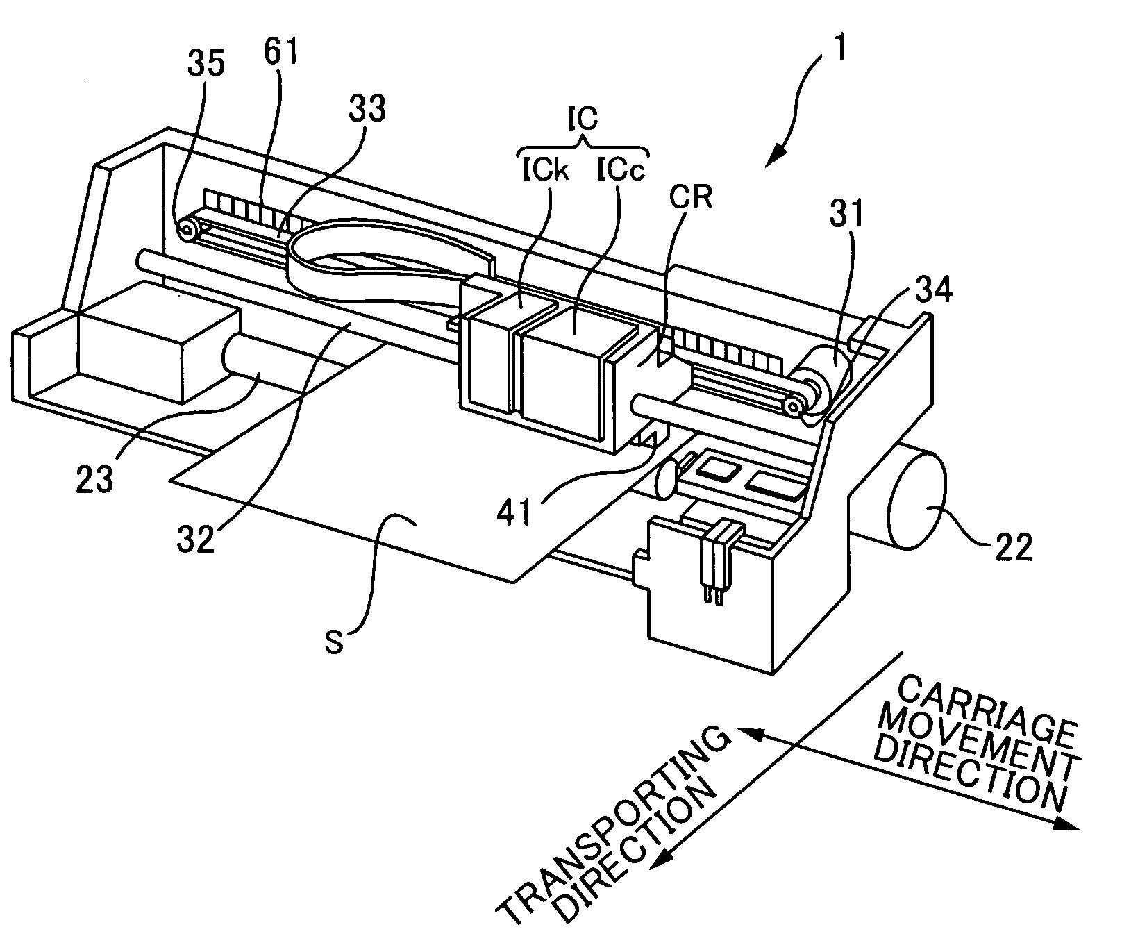
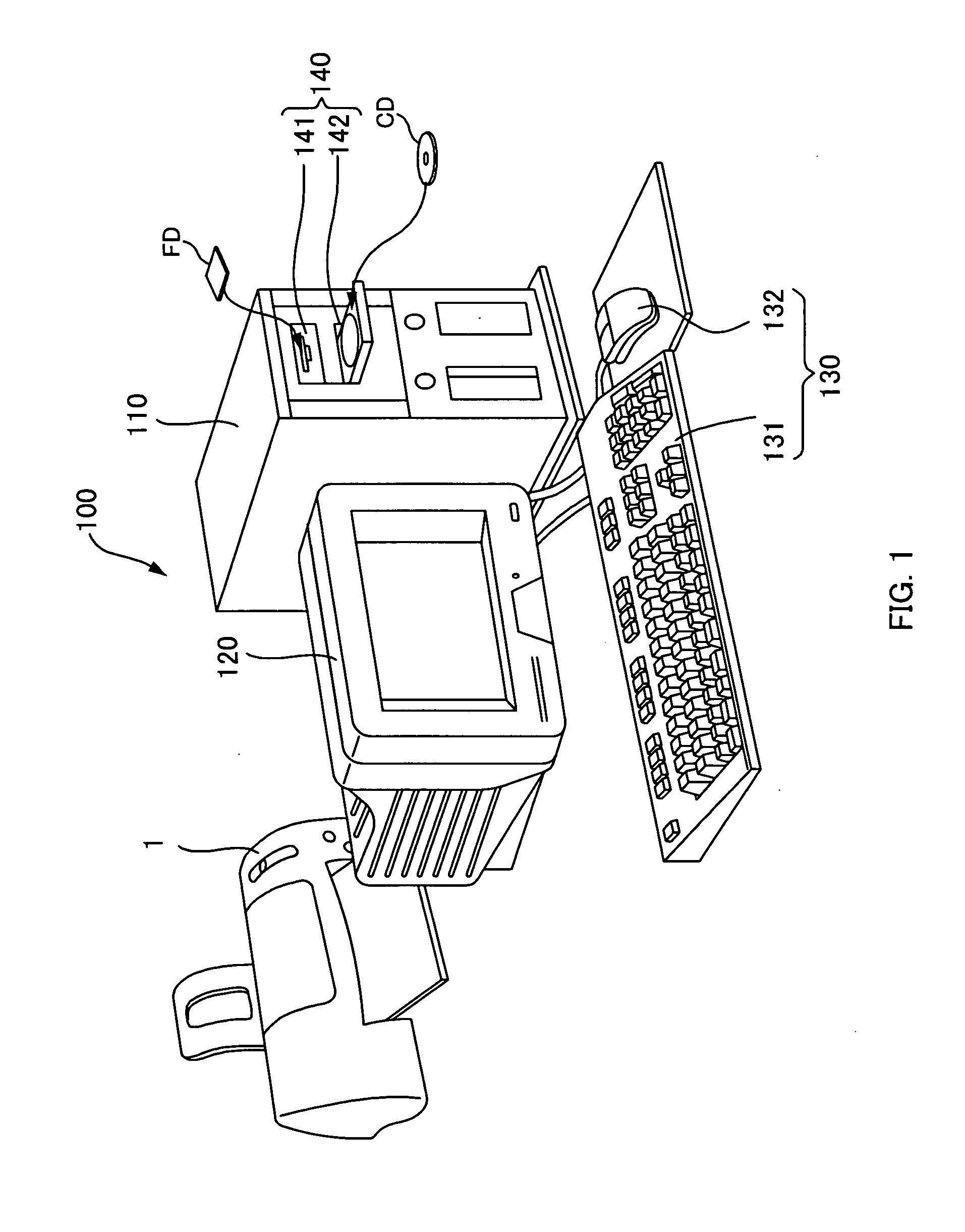
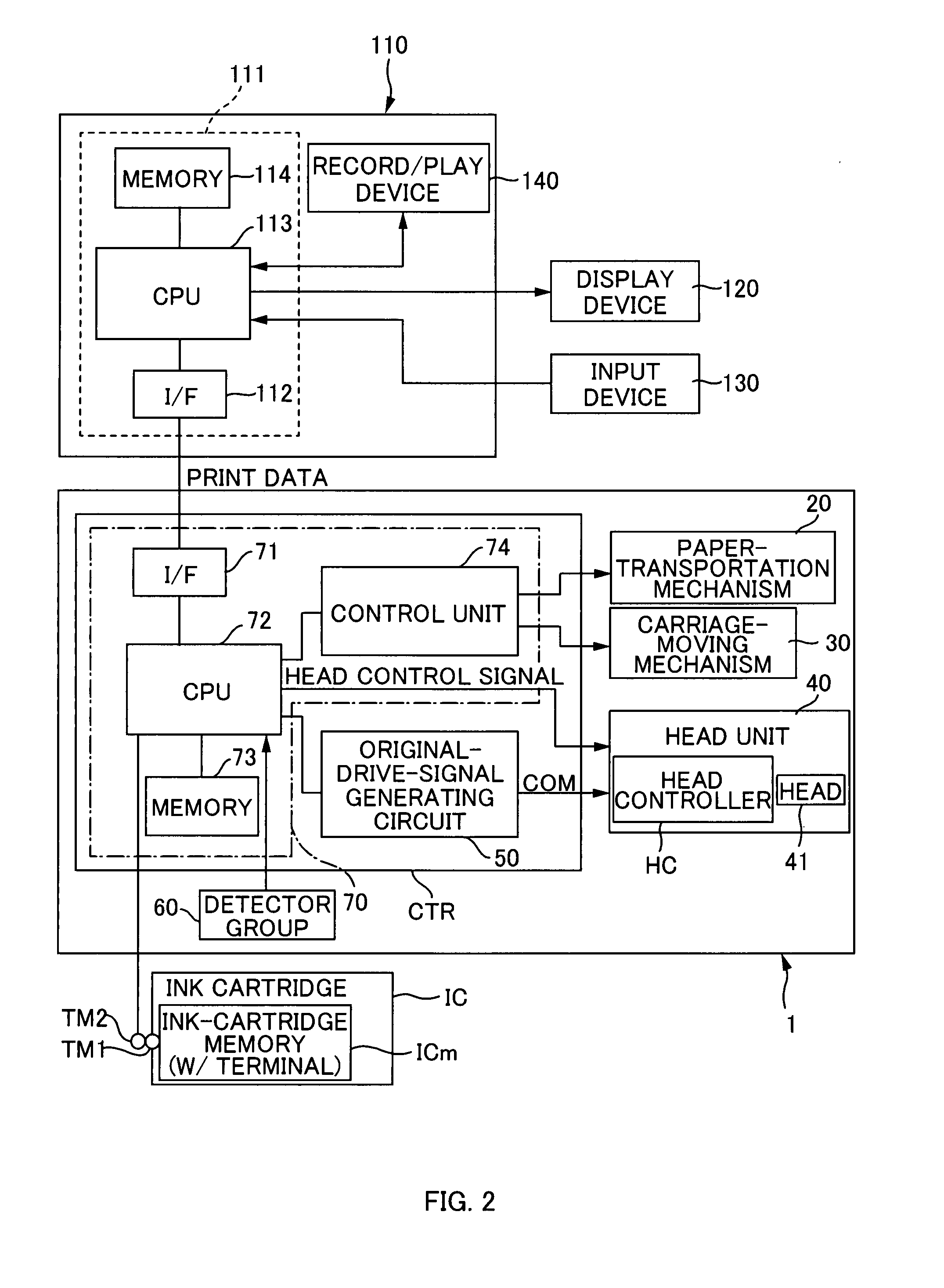
[0063] Configuration of Printing System 100

[0064] First, a printing apparatus is described with a printing system 100. Here, FIG. 1 is an explanatory diagram showing the configuration of the printing system 100. The illustrated printing system 100 has a printer 1 as the printing apparatus and a computer 110 as a printing control apparatus. Specifically, the printing system 100 has the printer 1, the computer 110, a display device 120, an input device 130, and a record / play device 140. The printer 1 prints an image on a medium, such as paper, cloth, film and the like. This section below describes an example of a sheet of paper S, which is a typical medium (see FIG. 3A). The computer 110 is communicably connected to the printer 1. In order to make the printer 1 print an image, the computer 110 outputs print data corresponding to that image to the printer 1. This computer 110 has computer programs, such as an application program and a printer driver, installed thereon....

Example

Second Embodiment

[0160] In the printing system 100 of the above-mentioned first embodiment, for a medium dot of the light ink and a small dot of the dark ink, the same drive pulse (the third drive pulse PS3) is used, and for a large dot of the light ink and a medium dot of the dark ink, the same drive pulses (the first drive pulse PS1 and the third drive pulse PS3) are used. With respect to this point, only for a large dot of the light ink and a small dot of the dark ink, a same drive pulse may be used. The printing system 100 of the second embodiment that is configured as mentioned above is described below.

[0161] Here, FIG. 15 is an explanatory diagram showing the original drive signal COM in the printing system 100 in the second embodiment.

[0162]FIG. 16A is a diagram showing drive signals generated in ejection of the light cyan ink and the light magenta ink, for each tone level.

[0163]FIG. 16B is a diagram showing drive signals generated in ejection of the dark cyan ink, the da...


PUM


Abstract

In printing of multi-level darkness/lightness of a certain color, which is performed with a dark ink and a light ink of the certain color, graininess is improved. A printing method includes generating a plurality of types of drive signals, and ejecting the dark ink and the light ink from a head, an amount of each ink varying for each dot tone value. In generation of a plurality of the types of the drive signals, a plurality of the types of drive signals are generated, where a waveform section that is for the dark ink of the certain color and that corresponds to a minimum dot tone value in ejection of ink is different from a waveform section that is for the light ink of the certain color and that corresponds to the minimum dot tone value, and where a waveform section that is for the dark ink of the certain color and that corresponds to a maximum dot tone value is different from a waveform section that is for the light ink of the certain color and that corresponds to the maximum dot tone value. In ejection of the dark ink and the light ink from the head, a drive signal that is generated based on a type of the dot tone value designated according to a size of a to-be-formed dot and based on a type of the ink is applied to an element that is provided on the head and that performs an operation for ejecting ink.

Description

CROSS-REFERENCE TO RELATED APPLICATIONS [0001] The present application claims priority from Japanese Patent Application No. 2006-14343 filed on Jan. 23, 2006, which is herein incorporated by reference. BACKGROUND [0002] 1. Technical Field [0003] The present invention relates to printing apparatuses and printing methods. [0004] 2. Related Art [0005] As a so-called inkjet printing apparatus, which performs printing by ejecting ink from a head, there are a printer, a plotter, or a facsimile, for example. Among printing apparatuses of this kind, there are printing apparatuses that control operations of elements provided in a head by drive signals and that eject ink; wherein an amount of the ink is different depending on a dot tone level that is based on a size of a to-be-formed dot (see JP-A-10-193587, for example). The above-mentioned apparatuses perform such control using four dot tone levels that consist of non-formation of a dot, a small dot, a medium dot, and a large dot. Therefore...

Claims


Application Information

Patent Timeline
IPC IPC(8): G06K15/10
CPCB41J2/04508B41J2/0458B41J2/04581H04N1/4057B41J2/04593B41J2/2103H04N1/40087B41J2/04588
Inventor HOSHIYAMA, YOSHIKONUNOKAWA, HIROKAZUSATO, AKITO
Owner SEIKO EPSON CORP
Why Eureka
Try Eureka