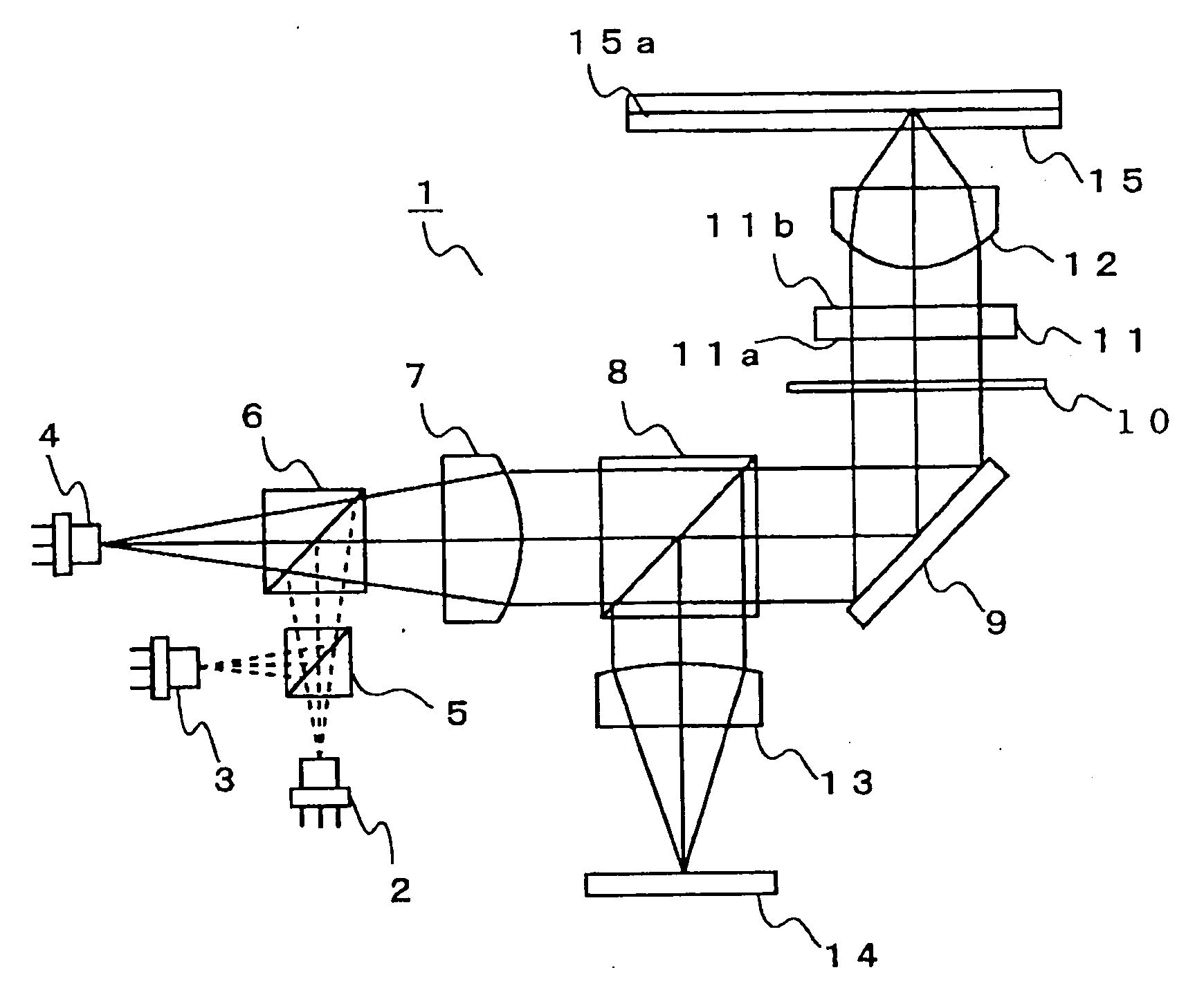
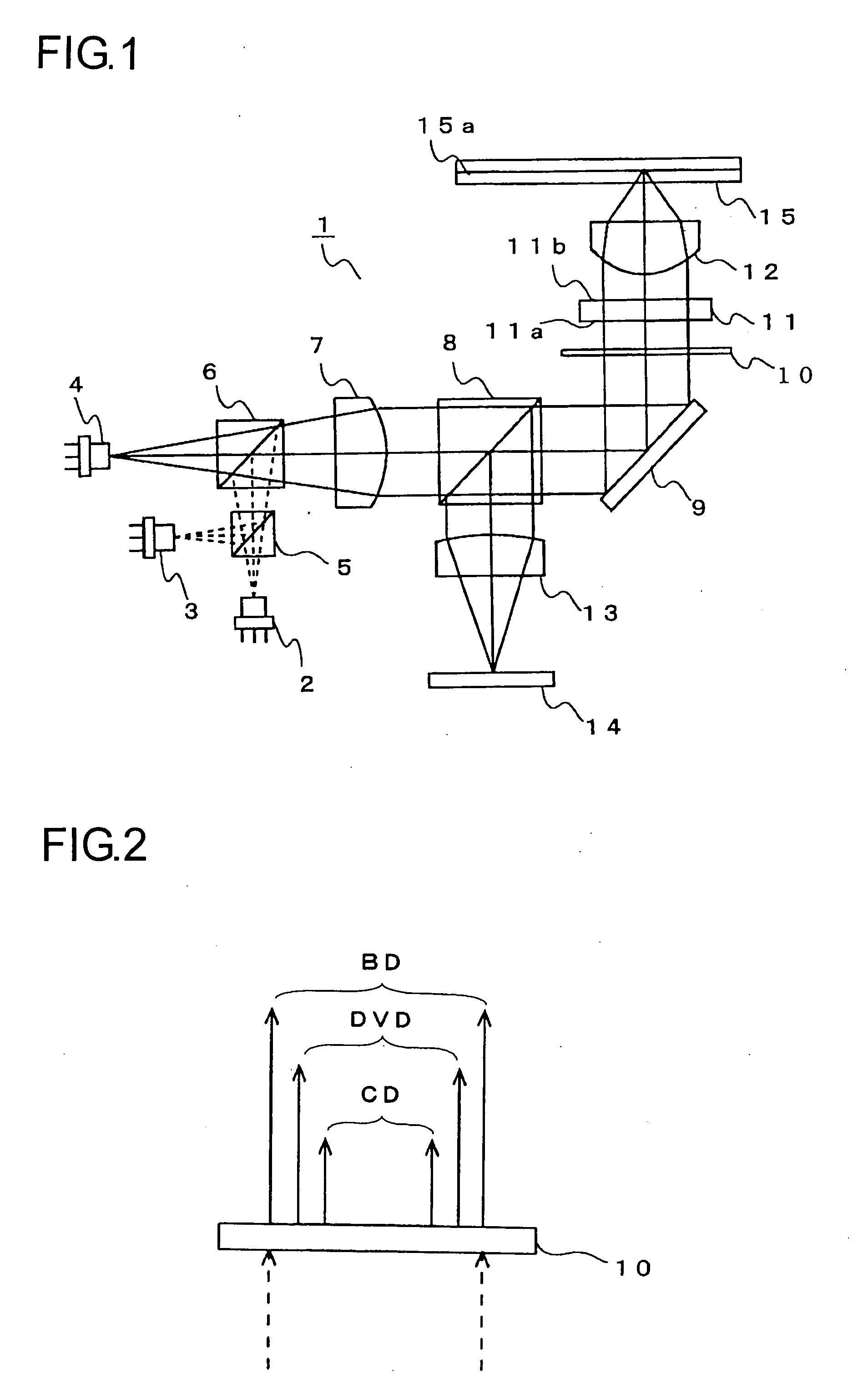
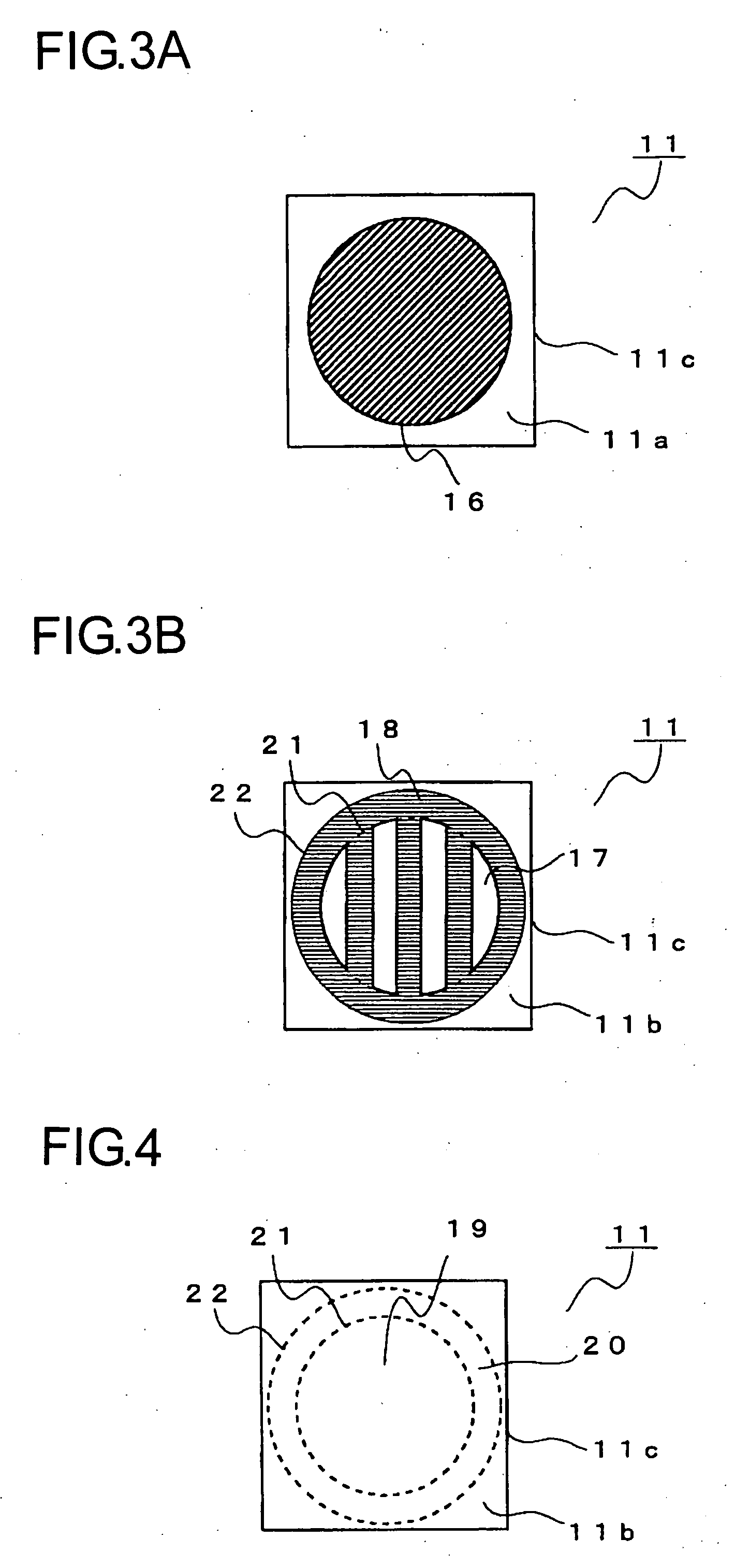
[0013]In view of the above described problem it is an object of the present invention to provide an optical
pickup device that supports a plurality of types of optical
recording media and is equipped with a single diffraction element for obtaining predetermined diffracted light of a plurality of light beams having different wavelengths, in which usage efficiency of light in the diffraction element can be improved.
[0019]According to first structure of the present invention, the optical pickup device, which is equipped with a single diffraction element that can obtain predetermined diffracted light from each of a plurality of light beams having different wavelengths, has a structure in which a part of the diffraction area is not disposed at unnecessary position when a plurality of types of diffraction areas are formed on one surface, by utilizing that diameters of light beams that pass through the diffraction element are different for different wavelengths of the light beams. Therefore, it is possible to obtain diffracted light effectively from each of the light beams having different wavelengths. As a result, usage efficiency of light in the diffraction element can be improved.
[0020]Moreover, according to the second structure of the present invention, usage efficiency of light in the diffraction element can be improved because the first region and the second region have the structure in which diffracted light can be obtained in the diffraction element effectively in the optical pickup device having the second structure.
[0021]Moreover, according to the third structure of the present invention, it is possible that the light beam entering the diffraction element can be distributed equally to the diffraction areas because the different types of diffraction areas are arranged alternately and repeatedly in a stripe manner in the region where two types of diffraction areas arranged when two types of diffraction areas are formed on one surface in the optical pickup device having the first or the second structure described above. Therefore, diffracted light with little deviation in its shape and quality can be obtained from the light beams having different wavelengths.
[0022]Moreover, according to the fourth structure of the present invention, it is possible to obtain appropriate quantity of light effectively for the diffracted light of light beams having different wavelengths because the combination of the light beams that generate predetermined diffracted light in the diffraction area is a combination of the light beams in which a difference of
diameter between light beams entering the diffraction element becomes maximum when two types of diffraction areas are formed on one surface in the optical pickup device having any one of the first to the third structures described above.
[0023]Moreover, according to the fifth structure of the present invention, the optical pickup device, which is equipped with a single diffraction element that can obtain predetermined diffracted light from each of three light beams having different wavelengths, has a structure in which a part of the diffraction area is not disposed at unnecessary position when the two types of diffraction areas are formed on one surface, by utilizing that diameters of light beams that pass through the diffraction element are different for different wavelengths of the light beams. Therefore, it is possible to obtain diffracted light effectively from each of the light beams having different wavelengths, and usage efficiency of light in the diffraction element can be improved. In addition, since the combination of the light beams that generate predetermined diffracted light in the diffraction area is a combination of the light beams in which a difference of
diameter between light beams entering the diffraction element becomes maximum when two types of diffraction areas are formed on one surface, it is possible to obtain appropriate quantity of light effectively for the diffracted light of light beams having different wavelengths. In addition, since different types of diffraction areas are repeated alternately in a stripe manner in the region where two types of diffraction areas are arranged when the two types of diffraction areas are formed on one surface, it is possible that the light beam entering the diffraction element can be distributed equally to the diffraction areas. Therefore, diffracted light with little deviation in its shape and quality can be obtained from the light beams having different wavelengths.


