
Photocatalyst air purification module and air purifier formed thereby

A technology of air purification and photocatalyst, which is applied in the field of photocatalyst air purification module and the air purification device composed of it, can solve the problems of low quantum efficiency of catalytic reaction, low utilization rate of light source, and guaranteed air flow, so as to enhance the effect of air purification and improve Lighting efficiency, the effect of increasing the contact area

Active Publication Date: 2012-11-28
广东科立盈光电技术有限公司
View PDF8 Cites 1 Cited by
  • Summary
  • Abstract
  • Description
  • Claims
  • Application Information

AI Technical Summary

Problems solved by technology

The bottleneck of the existing photocatalyst air purification technology lies in the low quantum efficiency of the catalytic reaction, that is, the ratio of the effective electrons or holes generated to the incident photons is low, and there is a defect of low light source utilization. Improving the quantum efficiency of the photocatalytic reaction is an improvement. The key to photocatalyst air purification technology
In the existing photocatalyst air purification equipment, improving the photocatalyst reaction efficiency and ensuring the air flow are a pair of unsolvable contradictions, and we can only choose one of the two.
At present, in the existing products, the structure of the photocatalyst carrier (the photocatalyst material is loaded on the photocatalyst carrier) usually adopts two layout schemes: perpendicular to the light and parallel to the vertical arrangement: 1. The photocatalyst support adopts the layout perpendicular to the light At this time, the photocatalyst carrier is divided into two types: network structure and sponge structure. Change) It is difficult to ensure the air flow under the effective photocatalyst reaction efficiency. Although the sponge-like structure has a good air purification effect, it cannot make full use of the material; It is a great waste, and the photocatalyst reaction efficiency is low
[0003] Existing studies have shown that the photocatalytic reaction mainly occurs on the surface or near the surface of the photocatalyst material. In the traditional design, the airflow simply passes through the photocatalytic carrier, and it is difficult for the pollutants in the gas to fully contact with the hydrogen and oxygen radicals to be released. purify
In the traditional design, in order to obtain a better air purification effect, the gas flow rate, light energy utilization rate and material utilization rate will be sacrificed, which is far from meeting the environmental protection requirements

Method used


Image

  • Photocatalyst air purification module and air purifier formed thereby
  • Photocatalyst air purification module and air purifier formed thereby
  • Photocatalyst air purification module and air purifier formed thereby

Examples


Embodiment 1

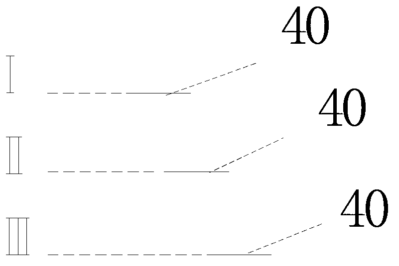
[0030] The photocatalyst air purification module of the present invention is composed of three photocatalyst carriers and a light source. The photocatalyst carrier is provided with a photocatalyst layer. The photocatalyst carrier is made of ceramics. The photocatalyst layer is a nano-titanium dioxide layer. on the photocatalyst carrier. Such as figure 1 As shown, the photocatalyst carrier is staggered in such a way: three photocatalyst carriers 40 are arranged in three layers, and the space between layers is parallel, and the photocatalyst carrier 40 between adjacent two layers has a vertical projection on the same plane. Overlapping (the plane where the vertical projection is located is parallel to the space of the photocatalyst supporting layer), but not completely overlapping.

[0031] The photocatalyst air purification modules arranged in this way are arranged in the casing, and an air inlet and an air outlet are arranged on the casing, and the light source is connected t...

Embodiment 2

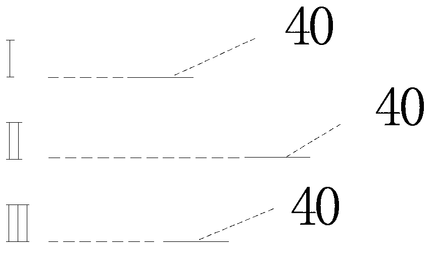
[0036] The photocatalyst air purification module of the present invention is composed of three photocatalyst carriers and a light source. The photocatalyst carrier is provided with a photocatalyst layer. The photocatalyst carrier is made of ceramics. The photocatalyst layer is a nano-titanium dioxide layer. on the photocatalyst carrier. Such as figure 2 As shown, the photocatalyst carrier is staggered in such a way: three photocatalyst carriers 40 are arranged in three layers, and the space between the layers is parallel, and the photocatalyst carrier 40 between adjacent two layers has no vertical projection on the same plane. Overlapping (the plane where the vertical projection is located is parallel to the space of the photocatalyst carrier layer), the vertical projections of the photocatalyst carrier 40 in the interlayer (such as the first layer and the third layer) on the same plane overlap, but do not overlap.

[0037] The photocatalyst air purification modules arranged...

Embodiment 3

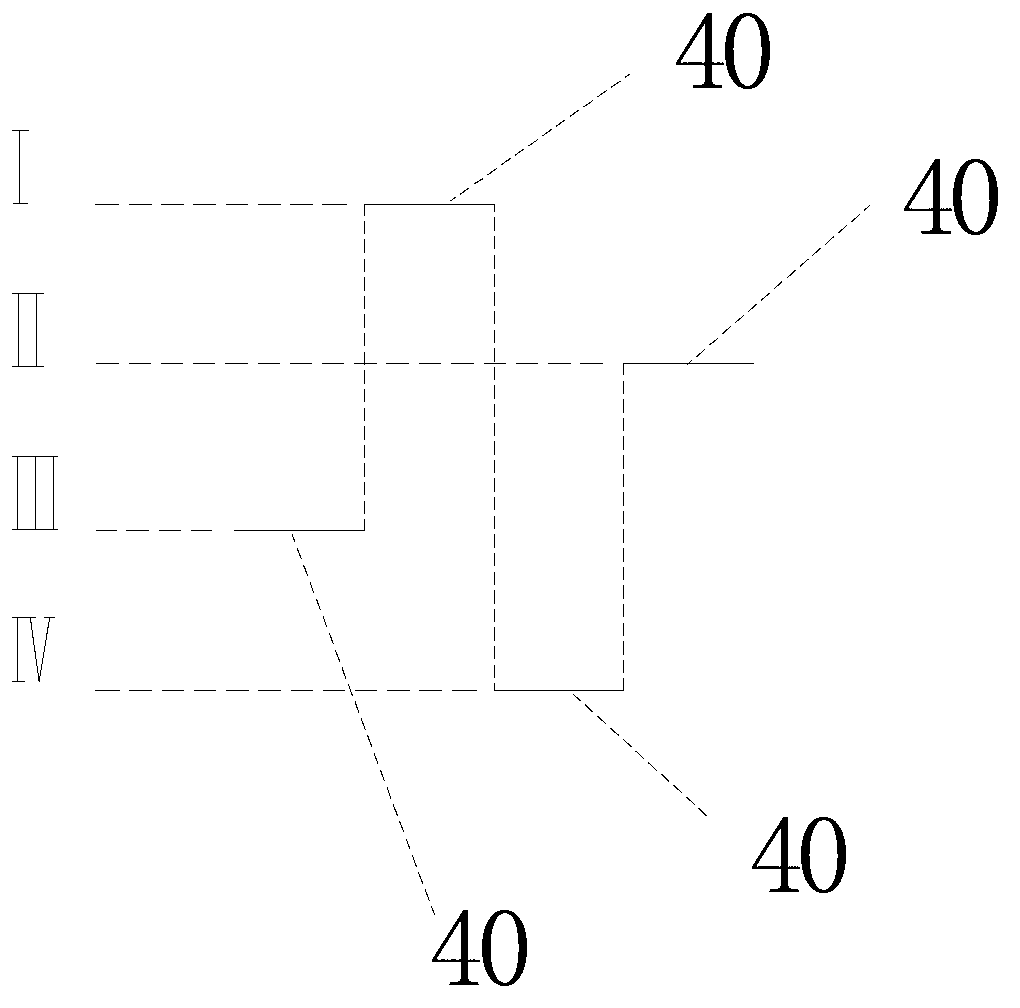
[0042] The photocatalyst air purification module of the present invention is composed of four photocatalyst carriers and a light source. The photocatalyst carrier is provided with a photocatalyst layer. The photocatalyst carrier is made of ceramics. The photocatalyst layer is a nano-titanium dioxide layer. irradiated on the photocatalyst carrier. Such as image 3 As shown, the photocatalyst carrier is staggered in such a way: four photocatalyst carriers 40 are arranged in four layers, and the space between layers is parallel, and the vertical projections of any two layers of photocatalyst carriers 1 on the same plane do not overlap, and The vertical projections of all the photocatalyst carriers on the same plane are seamlessly connected, and the plane where the vertical projections are located is parallel to the space of the photocatalyst carrier layers. The four photocatalyst carriers 40 are all square, and the vertical projection of the four photocatalyst carriers 40 on the...


PUM


Abstract

The invention provides a photocatalyst air purification module comprising a light source and photocatalyst bearing carriers which are provided with photocatalyst layers. The photocatalyst air purification module is characterized in that the photocatalyst bearing carriers are arranged in a layered mode, spaces among layers are parallel, the photocatalyst bearing carriers among layers are in crossed arrangement; and the light source irradiates the photocatalyst bearing carriers. The invention also provides an air purifier formed by the photocatalyst air purification moudle. The photocatalyst air purification moudle provided by the invention has the advantages of good light illumination efficiency and good air purification effect.

Description

technical field [0001] The invention relates to an air purification module, in particular to a photocatalyst air purification module and an air purification device composed of the same. Background technique [0002] Photocatalyst material is a general term for a class of photocatalytic semiconductors represented by TiO2, which can excite electrons under light irradiation conditions, and the formed electrons and holes react with oxygen and water molecules in the air to form highly oxidizing Hydroxyl free radicals can kill bacteria in the air and degrade organic pollutants to achieve the purpose of purifying the air. The bottleneck of the existing photocatalyst air purification technology lies in the low quantum efficiency of the catalytic reaction, that is, the ratio of the generated effective electrons or holes to the incident photons is low, and there is a defect of low utilization rate of the light source. Improving the quantum efficiency of the photocatalytic reaction is ...

Claims


Application Information

Patent Timeline
IPC IPC(8): A61L9/18A61L9/22A61L9/20B01D53/76B01D53/44
Inventor 张怡
Owner 广东科立盈光电技术有限公司
Learn More