Heatable ice perforation device

a perforation device and perforation technology, which is applied in the field of heat dissipation devices, can solve the problem that the device does not have gasoline engine problems, and achieve the effect of reducing the number of perforation devices

Inactive Publication Date: 2007-08-16
PERIARD LEE ROBERT
View PDF12 Cites 7 Cited by
  • Summary
  • Abstract
  • Description
  • Claims
  • Application Information

AI Technical Summary

Benefits of technology

[0018] Another embodiment of this invention is a heatable ice perforation device as set forth just above wherein at least one tank is supported in the third cylindrical housing. Each tank is connected to a gas manifold regulator and the gas manifold regulator is connected to a gas transport line. The gas transport line descends to the heat-generating element. The heat-generating element is a gas ring burner. There is an igniter wire connected to an igniter on one end and the opposite end descends and is located near the gas ring burner. There is a heat resistant plate positioned at or near the bottom of and above the gas ring burner. The control module contains the igniter ignition, a gas on and off valve and a gas ring burner on and off valve.

Problems solved by technology

The devices do not have gasoline engine related problems, such as messy gasoline, oil, and exhaust fumes, gas flooding, recoil rope problems or spring recoil problems, choke sticking and / or freezing, and no difficulty with spark plugs.

Method used


Image

  • Heatable ice perforation device
  • Heatable ice perforation device
  • Heatable ice perforation device

Examples


Embodiment Construction

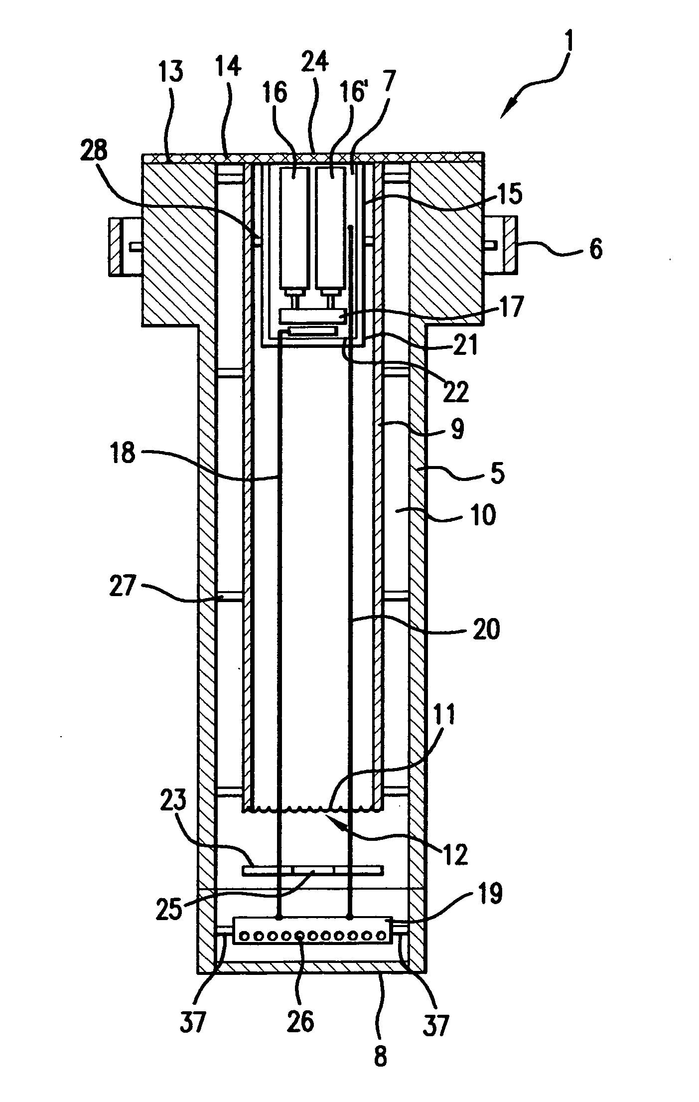
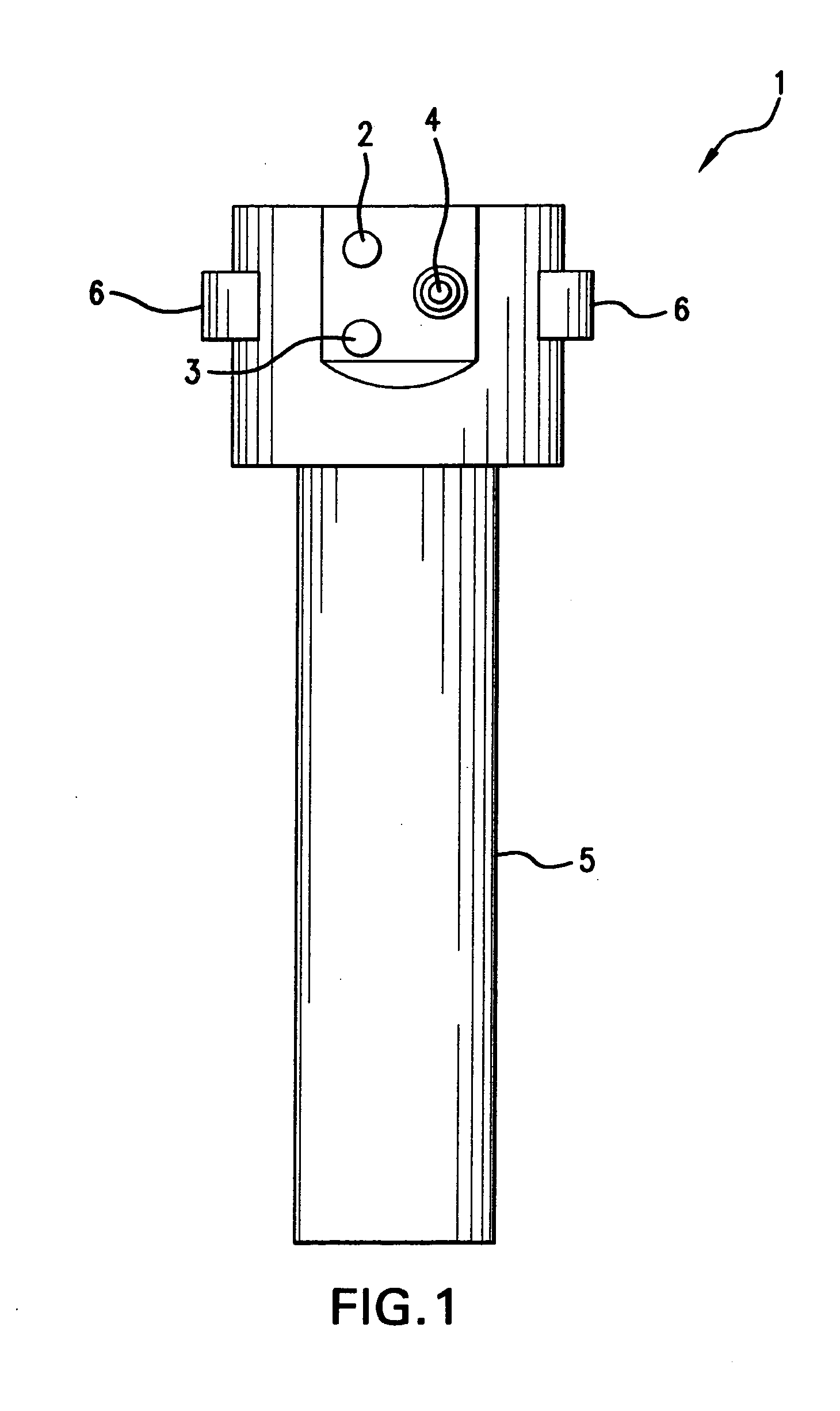
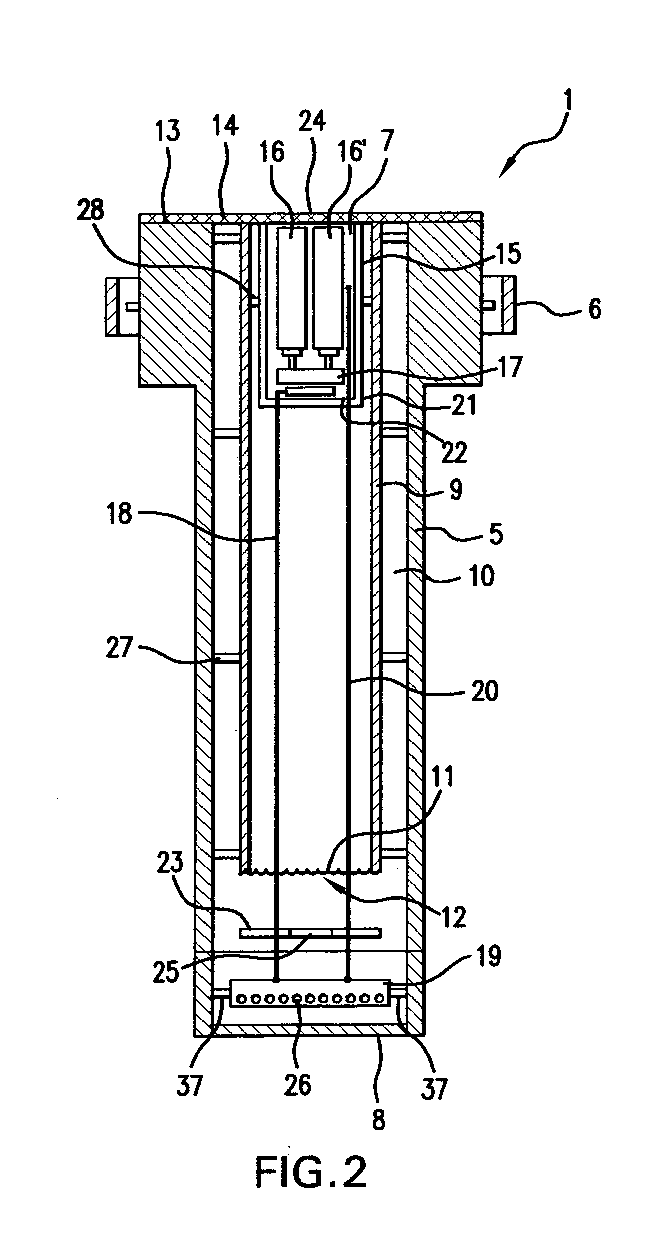
[0028] Turning now to FIG. 1, and for purposes of describing and illustrating the invention disclosed herein, there is shown a full side view of an ice penetration device 1 that is equipped with gas tanks (FIG. 2) as the energy source. In FIG. 1, there is shown an on / off valve 2 for the gas (also shown in FIG. 4), and an on / off valve 3 for the gas burner, along with a push button igniter 4 for igniting the gas (also shown in FIG. 4), all contained in the wall of the outside housing 5.

[0029] The overall size of the devices of this invention may be from about 24 inches to about 48 inches in height and about 6 to fourteen inches in diameter, it being understood that the devices do not have to circular, as they may be square, rectangular, triangular, and the like.

[0030] In FIG. 1, there is shown a gas on / off valve 2 and a burner on / off valve 3, along with a push button igniter 4 for igniting the gas the utility of which and the interaction of which will be discussed with reference to ...


PUM


Abstract

A heatable ice perforation device that is intended to provide for placing holes in ice in relatively quick time comprising a controllable heat source for heating a power head for melting ice.

Description

[0001] The invention disclosed and claimed herein deals with a heatable ice perforation device that is intended to provide for placing holes in ice in relatively quick time. BACKGROUND OF THE INVENTION [0002] There are many advantages to being able to place holes through ice. Some are business oriented, such as drilling for various minerals and oils, placement of defense devices under the ice, and for pleasure, for example, ice fishing. [0003] Many methods have been devised for placing holes in ice, among them, ice spuds that are manufactured from metals such as iron and steel that have one end sharpened for chopping the ice. Using one of these devices is very laborious and takes a fair amount of time to create an ice hole. [0004] Eventually, ice augers were developed that were manipulated by hand, in that, the devices had lower ends sharpened to a cutting edge, such as blades, and the upper end was provided with a handle that was rotatable to rotate the sharp end through the ice. U...

Claims


Application Information

Patent Timeline
Patent Type & Authority Applications(United States)
IPC IPC(8): F25C5/04
CPCE21B7/008A01K97/01
Inventor PERIARD, LEE ROBERT
Owner PERIARD LEE ROBERT
Why Eureka
Try Eureka