Friction stir welding apparatus and method of operating same

a friction stir welding and friction stir technology, applied in the direction of soldering apparatus, manufacturing tools, auxillary welding devices, etc., can solve the problems of increasing the production cost in the end, time and labor, etc., and achieve the effect of effectively arranging the rotary tool

Active Publication Date: 2007-08-16
HONDA MOTOR CO LTD
View PDF12 Cites 27 Cited by
  • Summary
  • Abstract
  • Description
  • Claims
  • Application Information

AI Technical Summary

Benefits of technology

[0015]With this construction, it is possible to effectively arrange the rotary tool and the roller in a position opposite to each other.

Problems solved by technology

This requires much time and labor, and thus increases the production cost in the end.

Method used


Image

  • Friction stir welding apparatus and method of operating same
  • Friction stir welding apparatus and method of operating same
  • Friction stir welding apparatus and method of operating same

Examples


Embodiment Construction

[0022]One preferred embodiment of the present invention will be described with reference to the accompanying drawings.

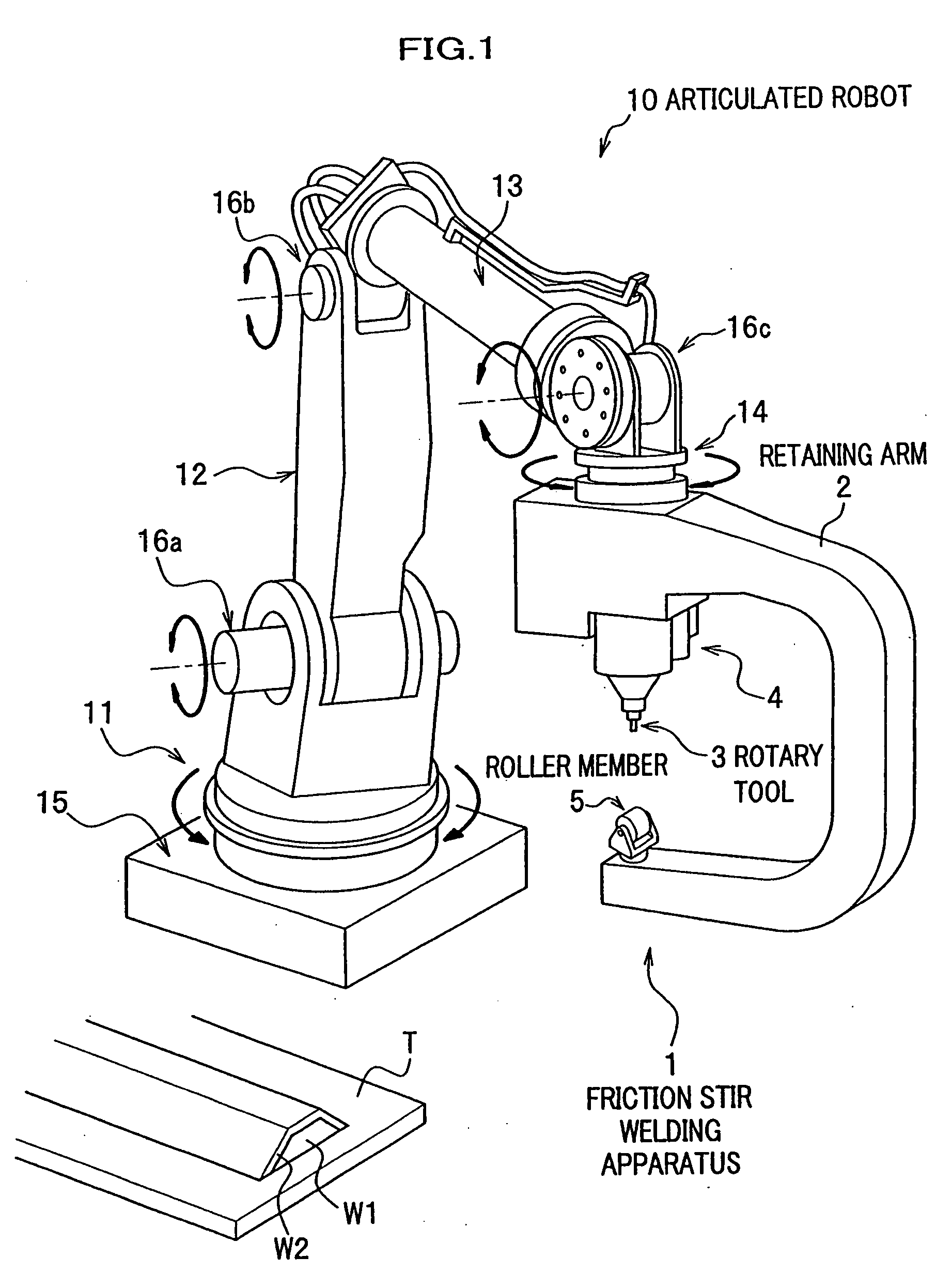
[0023]As seen in FIG. 1, a friction stir welding apparatus 1 is attached to a general-purpose articulated robot 10 and is movable in three-dimensional directions. At first, the articulated robot 10 will be described below.

Articulated Robot

[0024]The articulated robot 10 includes a turn table 11, and first, second and third arms (robot arm) 12, 13, 14 which are in this order joined together from the turn table 11 toward the distal end of the robot arm.

[0025]The turn table 11 is attached to a basement 15 installed on the installation surface and rotatable around an axis substantially extending in the direction perpendicular to the basement 15. The first arm 12 is attached to the turn table 11 through a first shaft member 16a which is pivotally supported on the turn table 11. The first arm 12 is therefore rotatable around the axis of the first shaft member 16a. The secon...


PUM

PropertyMeasurementUnit
plastic deformationaaaaaaaaaa
timeaaaaaaaaaa
shapeaaaaaaaaaa

Abstract

A friction stir welding apparatus and a method of operating the friction stir welding apparatus are disclosed. The friction stir welding apparatus includes a rotary tool whose extremity constitutes a probe, a retaining arm which supports the rotary tool, and a roller provided at a position of the retaining arm opposite the rotary tool. The method includes adjusting the retaining arm so as to position workpieces between the rotary tool and the roller while adjusting the roller to turn in a direction where a joint line of the workpieces extends, rotating the rotary tool and lowering the probe until the probe presses the workpieces, gradually inserting the probe into the joint line, and moving the probe along the joint line.

Description

CROSS REFERENCE TO RELATED APPLICATIONS[0001]This application claims the foreign priority benefit under Title 35, United States Code, §119(a)-(d) of Japanese Patent Applications No. 2006-024028 filed on Feb. 1, 2006 in the Japan Patent Office, the disclosure of which is herein incorporated by reference in its entirety.BACKGROUND OF THE INVENTION[0002]The present invention relates to a friction stir welding apparatus and a method of operating a friction stir welding apparatus. The Friction stir welding apparatus is usually attached to a distal end of an arm of an articulated robot.[0003]In recent years, friction stir welding has been widely used as a joint technology without causing a deformation of workpieces to be joined together due to heat generating in the welding process. Friction stir welding is a joining process for joining two members (workpieces) together along a joint line at a joint region (butted region) of the two workpieces by rotating and pressing a rotary tool agains...

Claims


Application Information

Patent Timeline
Patent Type & Authority Applications(United States)
IPC IPC(8): A47J36/02
CPCB23K2203/10B23K20/126B23K2103/10
Inventor SAYAMA, MITSURUMIYAHARA, TETSUYAFUKUCHI, FUMIAKI
Owner HONDA MOTOR CO LTD
Why Eureka
Try Eureka