Body vessel filter

a filter and body vessel technology, applied in the field of body vessel filter, can solve the problems of reducing filtering efficiency, difficult to visualize with accuracy the effectiveness of a vena, and exposing less efficient areas of the filter to blood flow at the center of the lumen

Inactive Publication Date: 2007-08-16
EV3
View PDF59 Cites 54 Cited by
  • Summary
  • Abstract
  • Description
  • Claims
  • Application Information

AI Technical Summary

Problems solved by technology

For good results, it is desired that the center of the filter remain near the center of the vessel, but often this is not easily controlled and the center of the filter may tilt to one side or the other of the lumen, thus exposing the less efficient areas of the filter to blood flow at the center of the lumen and reducing filtering efficiency.
Also, it is sometimes difficult to visualize with accuracy the effectiveness of a vena cava filter in filtering out blood clots.
Commonly, an imaging or contrast medium such as Hipaque® (a product of Winthrop Pharmaceutical) or Conray® (a product of Mallinckrodt) may be injected upstream from the filter (that is, inferior to the filter in the vena cava) in the course of obtaining a vena cavogram, but the contrast liquid often becomes diluted in the blood stream as it reaches the filter, preventing precise visualization of blood clots in the filter.

Method used


Image

  • Body vessel filter
  • Body vessel filter
  • Body vessel filter

Examples


Embodiment Construction

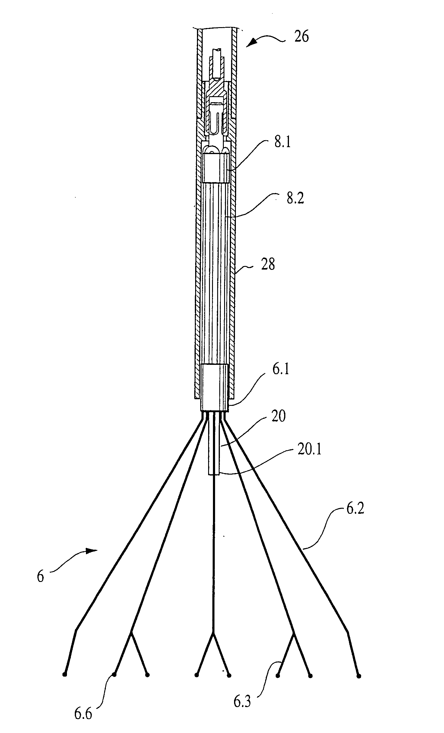
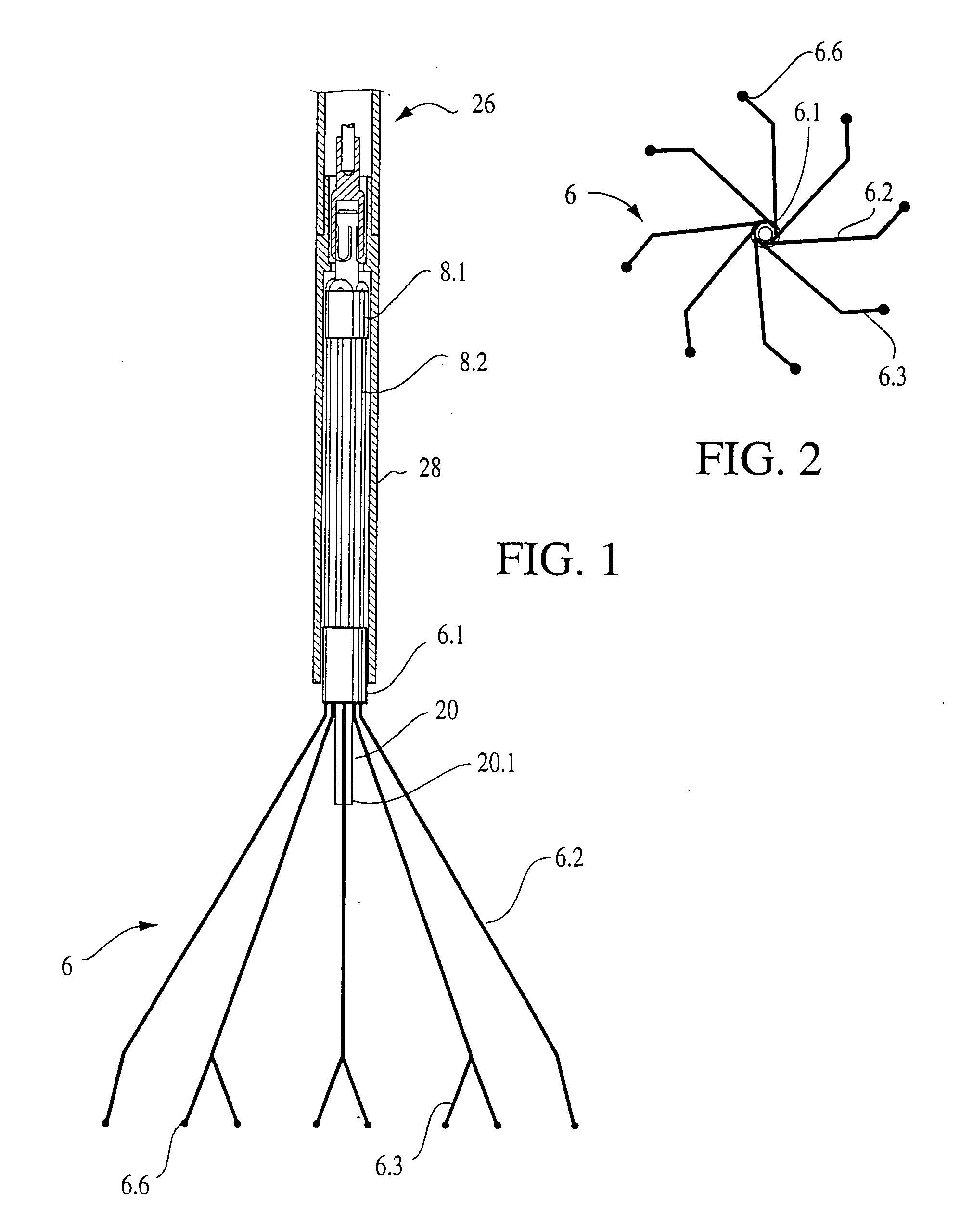
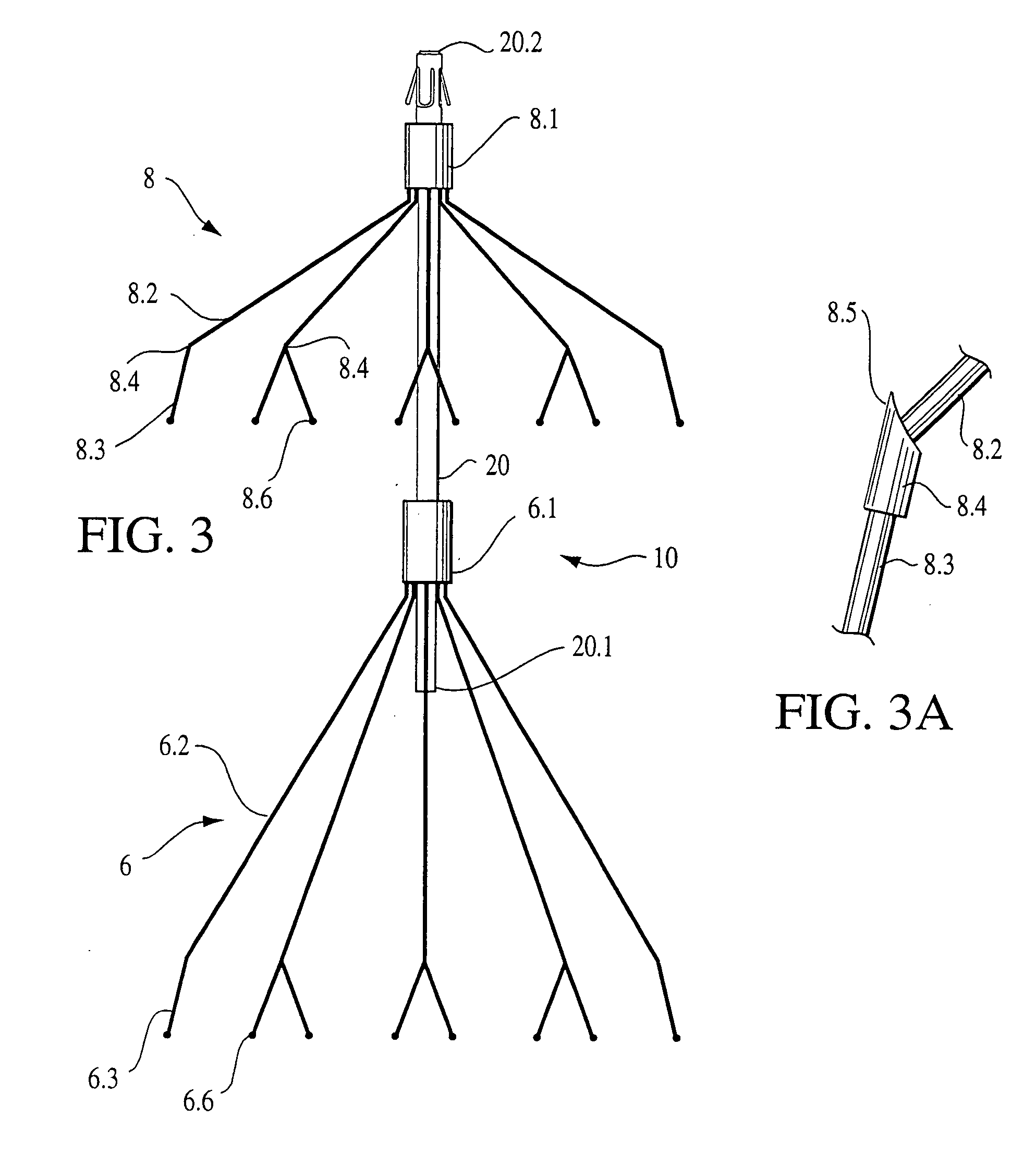
[0032] The invention provides a catheter-deliverable filter assembly for deploying a filter element in a vessel of the body, comprising: an elongated support having proximal and distal ends, the proximal end of the elongated support comprising a hook, separate filter and anchoring elements spaced axially along said support and each comprising a core carried by the support and a plurality of flexible, resilient wires having proximal portions attached to the core and distal portions extending distally of the core and configured to expand into resilient contact with walls of a vessel, said wires converging proximally toward their respective cores to define apices of the respective elements, said filter element being spaced distally of said anchoring element, and said anchoring element alone including gripping elements carried by distal portions of said wires and adapted to grip the walls of the vessel to anchor the filter assembly in the vessel. In one embodiment, the gripping elements...


PUM


Abstract

A catheter-deliverable filter assembly for deploying a filter element in a vessel of the body, comprising an elongated support having proximal and distal ends, the proximal end of the elongated support comprising a hook, separate filter and anchoring elements spaced axially along said support and each comprising a core carried by the support and a plurality of flexible, resilient wires having proximal portions attached to the core and distal portions extending distally of the core and configured to expand into resilient contact with walls of a vessel, said wires converging proximally toward their respective cores to define apices of the respective elements, said filter element being spaced distally of said anchoring element, and said anchoring element alone including gripping elements carried by distal portions of said wires and adapted to grip the walls of the vessel to anchor the filter assembly in the vessel.

Description

[0001] This application claims the benefit of U.S. Provisional Application No. 60 / 760,972, filed Jan. 20, 2006, entitled “Body Vessel Filter,” the contents of which are hereby incorporated by reference herein.BACKGROUND OF THE INVENTION [0002] Pulmonary embolism, in which emboli from any of various regions of the vascular system pass into the lungs, accounts for thousands of deaths each year in the United States. Blood clots from the lower extremities are commonly carried to the heart through the inferior vena cava, and thence to the lungs. [0003] Many patients with documented pulmonary embolism can be treated with anti-coagulants to prevent further formation of thrombi, but there are situations in which mechanical interruption of the inferior vena cava is the preferred method to prevent pulmonary embolism. To prevent blood clots from passing upwardly through the inferior vena cava, it has been suggested to place filters in the vena cava which filter out blood clots. An excellent bu...

Claims


Application Information

Patent Timeline
Patent Type & Authority Applications(United States)
IPC IPC(8): A61M29/00
CPCA61F2/01A61F2002/011A61F2230/0093A61F2230/005A61F2230/008A61F2002/016A61F2/0103A61F2/011
Inventor SEGNER, GARLAND L.DUDNEY, JOSHUA L.
Owner EV3
Why Eureka
Try Eureka