Intervertebral implant

Active Publication Date: 2007-08-16
SYNTHES USA
View PDF15 Cites 100 Cited by
  • Summary
  • Abstract
  • Description
  • Claims
  • Application Information

AI Technical Summary

Benefits of technology

[0019] In still another embodiment, the male and female dovetail guides taper off toward the lateral side surfaces of the implant that do not have connecting means. This facilitates the insertion of male dovetail guides into the female dovetail guides.
[0020] The longitudinal axis of the dovetail guides may be curved. The curvature of the dovetail guides allows inserting the center piece through a rotating gripping lever, whereby the space required for the introduction can be held to a minimum.
[0021] The longitudinal axis of the dovetail guides may alternatively be straight. The advantage of this embodiment is that the dovetail guides are easy to manufacture.
[0022] In yet another embodiment, the intervertebral implant is capable of being elastically deformed. The modular construction of the intervertebral implant makes it possible to insert center pieces o

Problems solved by technology

The disadvantage of this known implant is that during the implantation the already fully preassembled implant

Method used


Image

  • Intervertebral implant
  • Intervertebral implant
  • Intervertebral implant

Examples


Example

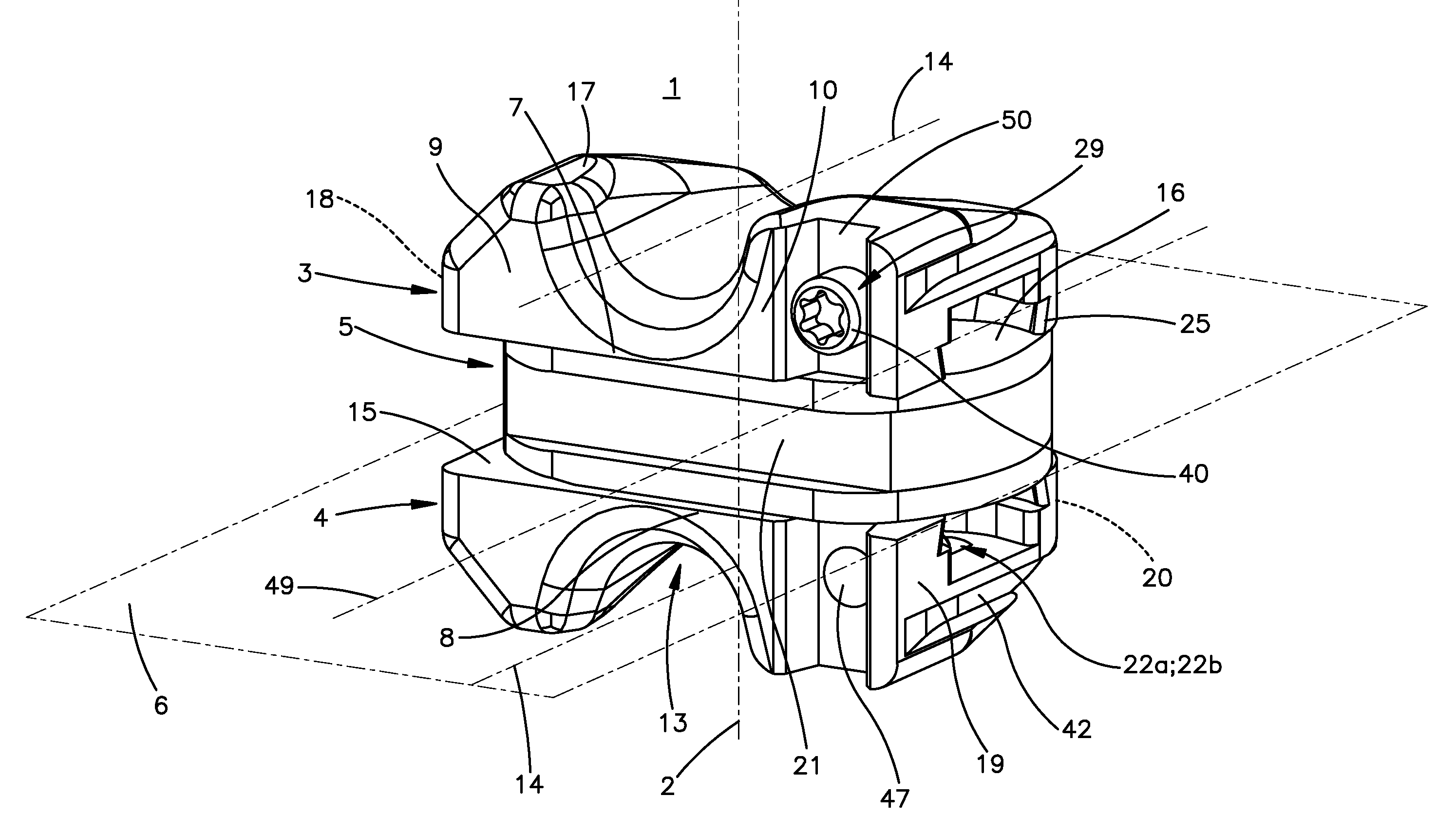
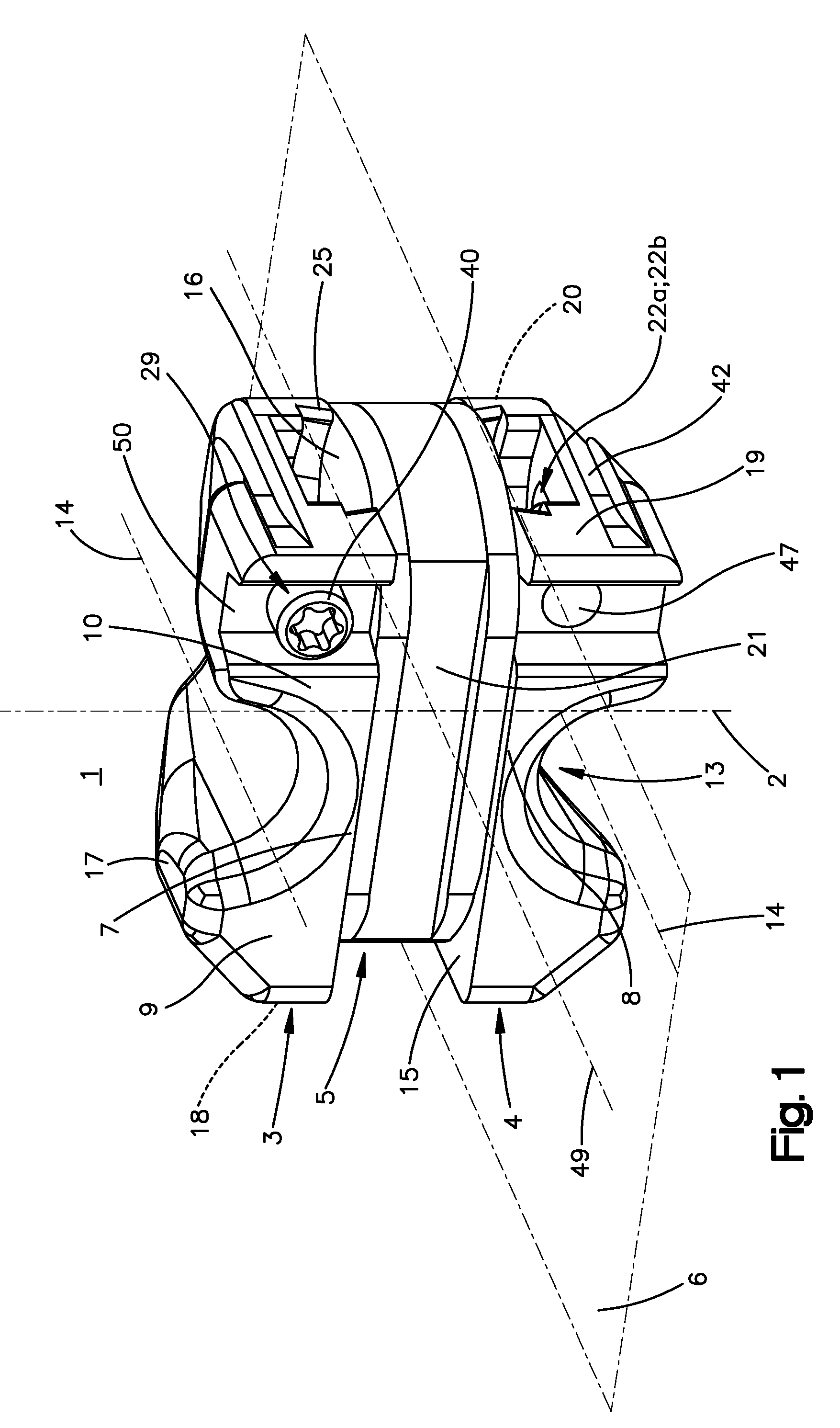
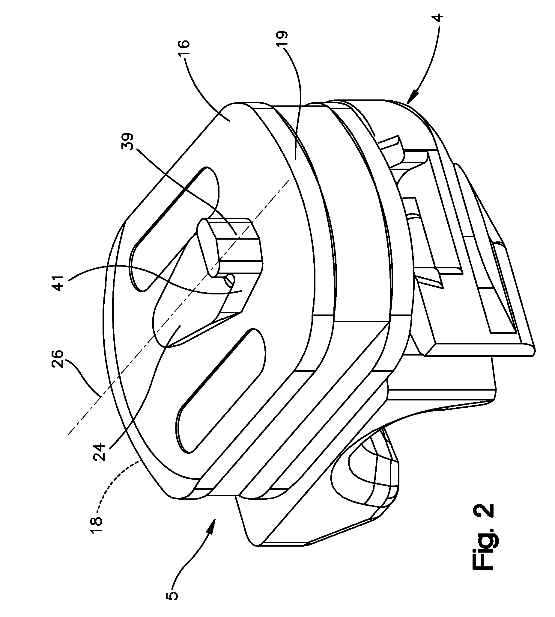
[0036] The implant 1 shown in the FIGS. 1 and 2 comprises essentially two U-shaped inserts 3;4 set across the central axis of the intervertebral implant 1, and a center piece 5 set between them. The inserts 3;4 are set with respect to a center plane 6 set orthogonally to the longitudinal axis 2 so that the crossbars 7 of the two inserts 3,4 are set up parallel to the central plane 6 and the free extremities 11;12 of the sidebars 9:10 are pointing away from the central plane 6.

[0037] A channel delimited by two sidebars 9;10 and a crossbar 7;8 of an insert 3;4 is adapted to receive a spinal process of a vertebral body, whereby the inserts 3;4 are inserted into the intervertebral inter-vertebral space so that the crossbars 7;8 are set between the spinal processes of two adjacent vertebral bodies. The channel axes 14 of the channels 13 are set across the center axis 2 in a front-to-rear direction, meaning that they run parallel to a transversal axis 49 that crosses the ventral and the ...


PUM


Abstract

An intervertebral implant has two U-shaped inserts set over each other with a center piece in between. The two inserts each have an opposing base surface, two lateral side surfaces, and a contact surface. The contact surface has a channel configured to receive a spinal process of a vertebral body. The center piece has two resting surfaces corresponding respectively to each contact surfaces. The contact and resting surfaces each have corresponding structures that can engage each other such that the U-shaped inserts can each be fastened in a detachable manner to the center piece. The U-shaped inserts each have on the same lateral side surface connecting means to fasten the inserts to gripping elements of a surgical instrument. And the first and second structures can be engaged or disengaged only by the lateral side surface fitted with the connecting means.

Description

CROSS-REFERENCE TO RELATED APPLICATION [0001] This is a continuation of pending International Application No. PCT / CH2004 / 000507, filed Aug. 13, 2004, the entire contents of which are expressly incorporated herein by reference thereto.FIELD OF THE INVENTION [0002] The invention relates to an intervertebral implant that serves as a spacer for two adjacent vertebral bodies in connection with a defective intervertebral disk, which would otherwise reduce the distance between the vertebral bodies. Because such implants restore the distance between the vertebral bodies, decompression of the bevel joints also results. BACKGROUND OF THE INVENTION [0003] Intervertebral implants of this kind are known from FR 2 7176 675 by Taylor. This known implant comprises two rigid inserts capable of being fastened to the spinal process of the vertebral bodies and an elastic center piece between them. The inserts have at their base surfaces barbed hook-like appendices which are cast into the elastic center...

Claims


Application Information

Patent Timeline
IPC IPC(8): A61F2/44
CPCA61B17/7062
Inventor HARTMANN, STEPHANSTUDER, ARMIN
Owner SYNTHES USA
Why Eureka
Try Eureka