Systems and methods for real-time system monitoring and predictive analysis

a real-time system and system monitoring technology, applied in the field of computer modeling and management of systems, can solve problems such as inability to apply real-time techniques, inability to reduce development costs and superior operation, and inability to use real-time techniques, etc., to achieve predictive failure analysis techniques that do not generally use real-time data that reflect actual system operation

Active Publication Date: 2007-08-16
POWER ANALYTICS CORP
View PDF22 Cites 144 Cited by
  • Summary
  • Abstract
  • Description
  • Claims
  • Application Information

AI Technical Summary

Benefits of technology

[0016]If the difference exceeds an alarm condition value, the analytics engine generates a warning message. If the difference is less than the alarm condition value but greater than a set value, the analytics engine generates a virtual system model calibration request. If the difference is less than the set value, the analytics engine continues monitoring the real-time ambient envi

Problems solved by technology

Such simulation techniques have resulted in reduced development costs and superior operation.
Design and production processes have benefited greatly from such computer simulation techniques, and such techniques are relatively well developed, but such techniques have not been applied in real-time, e.g., for real-time operational monitoring and management.
In addition, predictive failure analysis techniques do not generally use real-time data that reflect actual system operation.
It will be understood that such systems are highly complex, a complexity made even greater as a result of the required redundancy.
Once the facility is constructed, however, the design is typically only referre

Method used


Image

  • Systems and methods for real-time system monitoring and predictive analysis
  • Systems and methods for real-time system monitoring and predictive analysis
  • Systems and methods for real-time system monitoring and predictive analysis

Examples


Embodiment Construction

.”

BRIEF DESCRIPTION OF THE DRAWINGS

[0021]For a more complete understanding of the principles disclosed herein, and the advantages thereof, reference is now made to the following descriptions taken in conjunction with the accompanying drawings, in which:

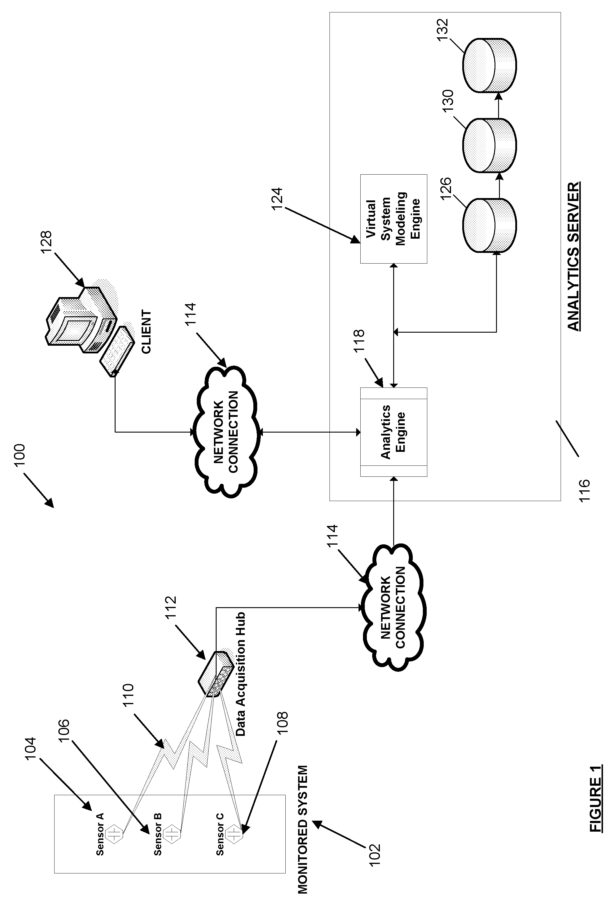
[0022]FIG. 1 is an illustration of a system for utilizing real-time data for predictive analysis of the performance of a monitored system, in accordance with one embodiment.

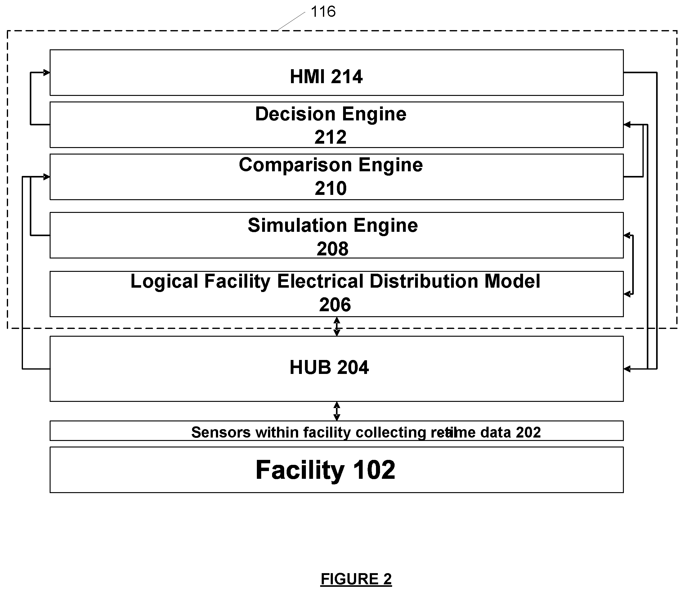
[0023]FIG. 2 is a diagram illustrating a detailed view of a analytics server included in the system of FIG. 1.

[0024]FIG. 3 is a diagram illustrating how the system of FIG. 1 operates to synchronize a the operating parameters between a physical facility and a virtual system model of the facility.

[0025]FIG. 4 is an illustration of the scalability of a system for utilizing real-time data for predictive analysis of the performance of a monitored system, in accordance with one embodiment.

[0026]FIG. 5 is a block diagram that shows the configuration details of the system ...


PUM


Abstract

A system for providing real-time modeling of an electrical system under management is disclosed. The system includes a data acquisition component, a virtual system modeling engine, and an analytics engine. The data acquisition component is communicatively connected to a sensor configured to provide real-time measurements of data output from an element of the system. The virtual system modeling engine is configured to generate a predicted data output for the element. The analytics engine is communicatively connected to the data acquisition system and the virtual system modeling engine and is configured to monitor and analyze a difference between the real-time data output and the predicted data output.

Description

APPLICATIONS FOR CLAIM OF PRIORITY[0001]This application claims the benefit under 35 U.S.C. §119(e) of U.S. Provisional Application No. 60 / 773,560 filed Feb. 14, 2006. The disclosure of the above-identified application is incorporated herein by reference as if set forth in full.BACKGROUND[0002]I. Field of the Invention[0003]The present invention relates generally to computer modeling and management of systems and, more particularly, to computer simulation techniques with real-time system monitoring and prediction of electrical system performance.[0004]II. Background of the Invention[0005]Computer models of complex systems enable improved system design, development, and implementation through techniques for off-line simulation of the system operation. That is, system models can be created that computers can “operate” in a virtual environment to determine design parameters. All manner of systems can be modeled, designed, and operated in this way, including machinery, factories, electr...

Claims


Application Information

Patent Timeline
IPC IPC(8): G06F17/50
CPCG05B23/0254G06F2217/04G06F17/5009G05B23/0297G06F2111/02G06F30/20
Inventor NASLE, ADIBNASLE, ALIMEAGHER, KEVIN
Owner POWER ANALYTICS CORP
Why Eureka
Try Eureka