Air Conditioned Seat Device And Air Conditioning System Using The Same

a seat device and seat technology, applied in the field of air conditioned seat devices and air conditioning systems, can solve the problems of limiting design, inability to provide small holes, and insufficient vaporization of steam to resolve steaminess

Inactive Publication Date: 2007-08-23
PANASONIC CORP
View PDF18 Cites 72 Cited by
  • Summary
  • Abstract
  • Description
  • Claims
  • Application Information

AI Technical Summary

Problems solved by technology

Consequently, sweat is not sufficiently vaporized to resolve steaminess.
For example, small holes cannot be provided in seat cover 4 where air from the air blower is not desired to blow out, which will largely constrain the design.

Method used


Image

  • Air Conditioned Seat Device And Air Conditioning System Using The Same
  • Air Conditioned Seat Device And Air Conditioning System Using The Same
  • Air Conditioned Seat Device And Air Conditioning System Using The Same

Examples


first exemplary embodiment

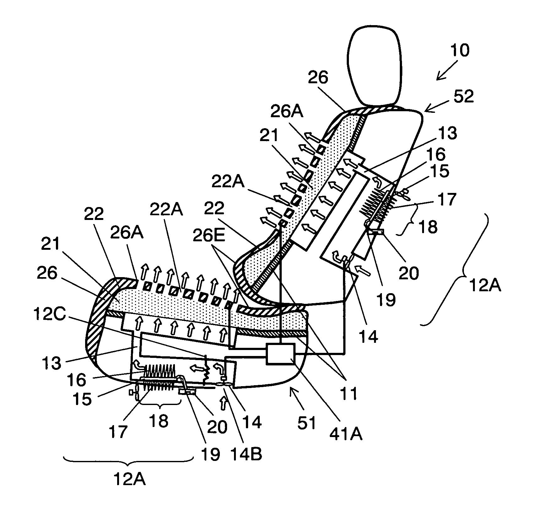
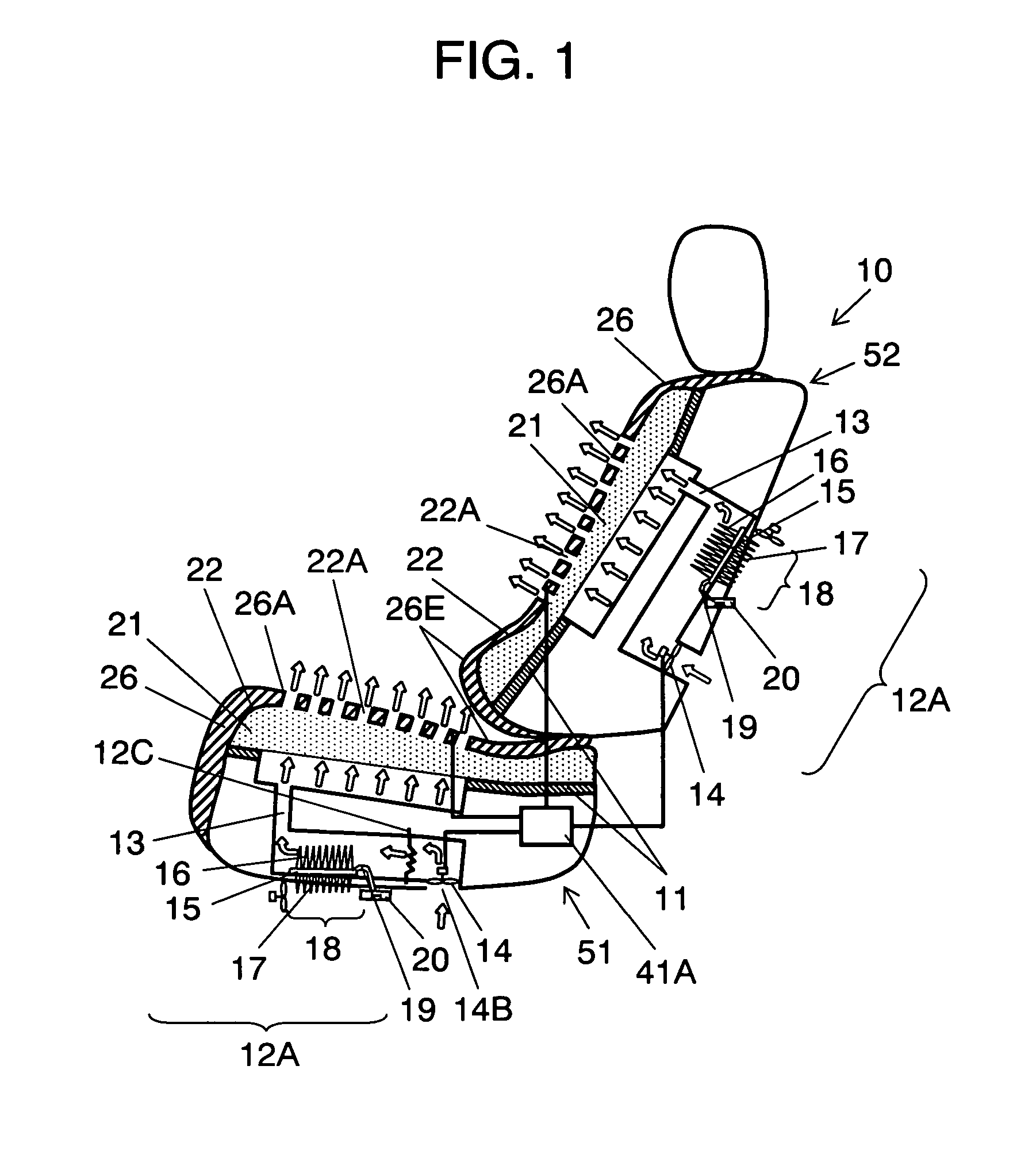
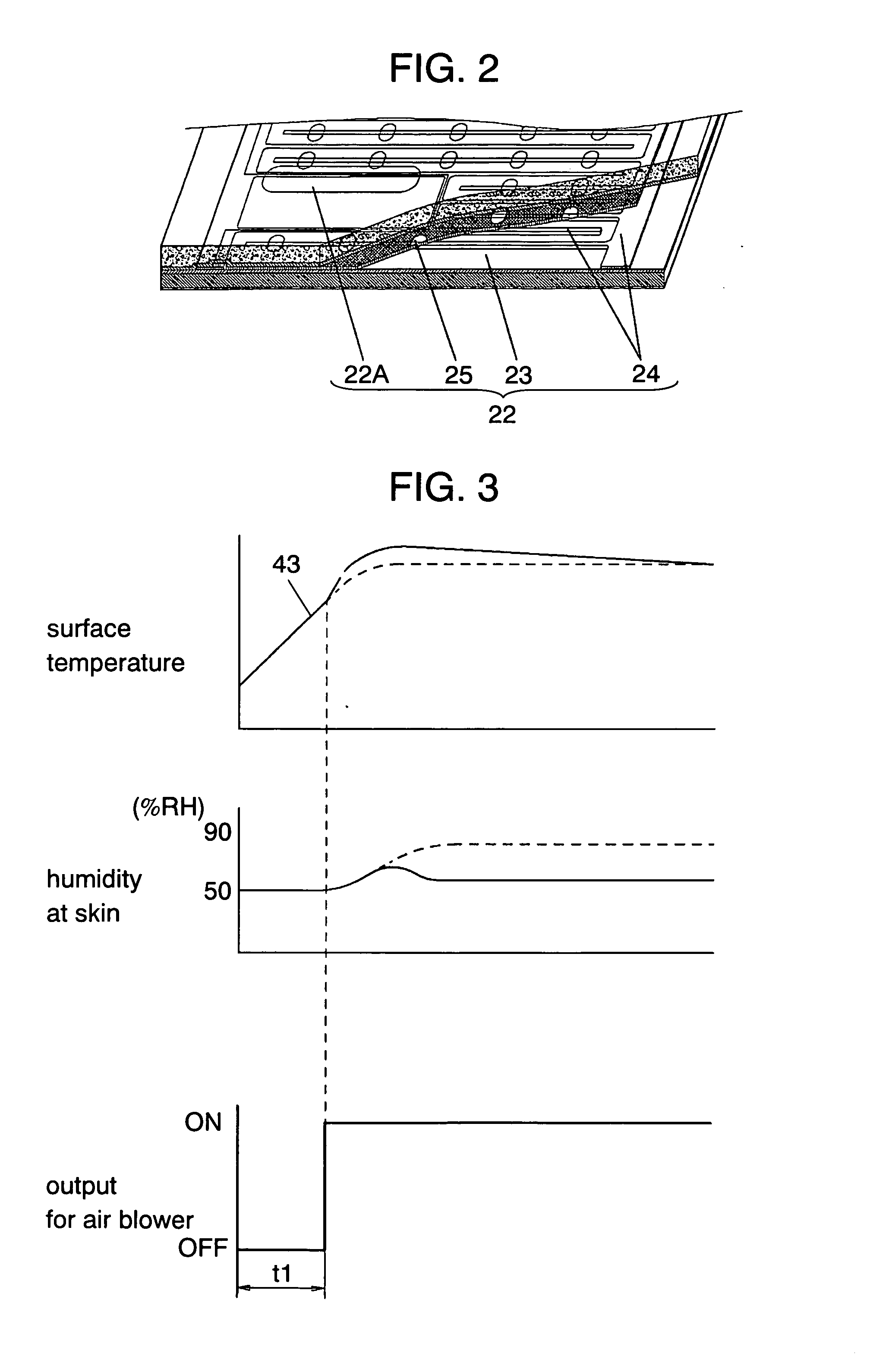
[0048]FIG. 1 is a sectional view of an air conditioned seat device according to the first exemplary embodiment of the present invention. FIG. 2 is a schematic diagram of a PTC heater used for the air conditioned seat device.

[0049] In seating portion 51, support member 11 forming the framework of the seat is provided with duct 13, a first duct passing air therethrough. Air conditioning unit (“conditioning unit” hereinafter) 12A for conditioning air is disposed halfway through duct 13. Air blower 14 such as a sirocco fan, a first air blower located at the bottom of the seat, takes air in through air inlet 14B provided in a part except seating surface 26E and sends the air to conditioning unit 12A. The conditioned air is sent toward seating surface 26E through duct 13. Support member 11 has elasticity in which the squash depth of the hip joint position is at least 30 mm and at most 200 mm when a typical human body weighing 75 kg is seated. The elasticity causes decreasing the concentr...

second exemplary embodiment

[0073]FIG. 5 is a longitudinal sectional view of an air conditioned seat device according to the second exemplary embodiment of the present invention. In this embodiment, surface temperature sensor (sensor, hereinafter) 42 made of such as a thermistor is arranged at a position where PTC heater 22 does not contact the human body and its temperature is equivalent to the surface temperature. That is, sensor 42 senses the temperature near skin 26, and then outputs a sensing signal to control unit 41B. Control unit 41B controls PTC heater 22 and air blower 14 according to the signal from sensor 42. Flexible pad 48 such as a thin sponge-like pad with high air permeability is disposed between PTC heater 22 and skin 26. The makeup otherwise is the same as that of the first exemplary embodiment.

[0074] In the above-mentioned makeup, control unit 41B drives air blower 14 when the surface temperature reaches “T1” after starting energization of PTC heater 22; and stops air blower 14 when the su...

third exemplary embodiment

[0078]FIG. 7 is a sectional view of an air conditioned seat device according to the third exemplary embodiment of the present invention, during a recycle-mode operation. FIG. 8 is a sectional view of the same during a dehumidify-mode operation.

[0079] In the present embodiment, air conditioning unit 12B is provided with dehumidifier 31 having a dehumidification agent (adsorbent) such as zeolite or silica gel with an adsorptive property. The dehumidification agent in dehumidifiers 31 is heated by heater units 32, which are first and second heater units such as electric heaters, through convection, radiation, or conduction. Vent 33 is further provided to communicate dehumidifier 31 to the outside of air conditioned seat device 10. Outlet air duct selector (selector, hereinafter) 35 which is a damper or the like is provided to be driven by stepping motor 34 or the like. Selector 35 closes duct 13 when vent 33 is opened and opens duct 13 when vent 33 is closed. Control unit 54 is connec...


PUM


Abstract

An air conditioned seat device has a support member, an air blower, a skin configured to form a seating surface, an air layer member, and an air-impermeable sheet member. The support member is provided with a duct for air. The air blower takes in air from the outside and passes the air through the duct. The skin passes air sent from the air blower. The air layer member, provided between the support member and skin, temporarily stores air supplied from the duct to form an air layer. The sheet member covering the air layer member is provided with an air flow-out opening configured to induce air to flow out from the air layer.

Description

[0001] This application is a U.S. national phase application of PCT International Application PCT / JP2005 / 004579TECHNICAL FIELD [0002] The present invention relates to an air conditioned seat device used for an automobile seat and an office chair, for example, that promptly provides a human body with a comfortable state even in an environment with uncomfortable outside air temperature. The invention particularly relates to an air conditioned seat device that provides a healthy comfortable sense of seating according to individual preference, and to an air conditioning system using the air conditioned seat device. BACKGROUND ART [0003] An air conditioned seat device with the structure as shown in FIG. 41 has been conventionally disclosed in the Japanese translation of PCT publication No. H9-505499, for example. In this air conditioned seat device, air duct 2 is formed in support member 1 inside the seat, and the outer side of support member 1 is covered with porous member 3. Porous sea...

Claims


Application Information

Patent Timeline
Patent Type & Authority Applications(United States)
IPC IPC(8): F25B21/02F25D17/04F25D17/06B60H1/32F25D23/12A47C7/74B60N2/00B60N2/56
CPCB60N2/5692B60N2/5635
Inventor YONENO, NORIYUKIKIKUTANI, FUMITAKANITTA, HIROAKINOZAWA, SHINTAROUSHIGEOKA, TAKEHIKOSHIRATAKE, AKIRAASAMI, NAOHITONAKANO, KOICHIARIMA, SATOSHI
Owner PANASONIC CORP
Why Eureka
Try Eureka