Thermostatic mixing valve

a technology of mixing valve and thermostat, which is applied in the direction of temperature control without auxiliaries, thin material handling, instruments, etc., can solve the problem of not allowing excess flow, and achieve the effect of easy disassembly and replacement, and convenient assembly and disassembly of the tmv

Inactive Publication Date: 2007-08-23
WATTS WATER TECH
View PDF19 Cites 24 Cited by
  • Summary
  • Abstract
  • Description
  • Claims
  • Application Information

AI Technical Summary

Benefits of technology

[0012] Among other aspects and advantages, the new and improved TMV of the present disclosure accommodates high-flow conditions as well as low-flow conditions. Yet the TMV of the present disclosure does not allow excess flow to bypass the sensing chamber containing the thermal motor. Even at high flow rates, therefore, the TMV accurately mixes fluid.
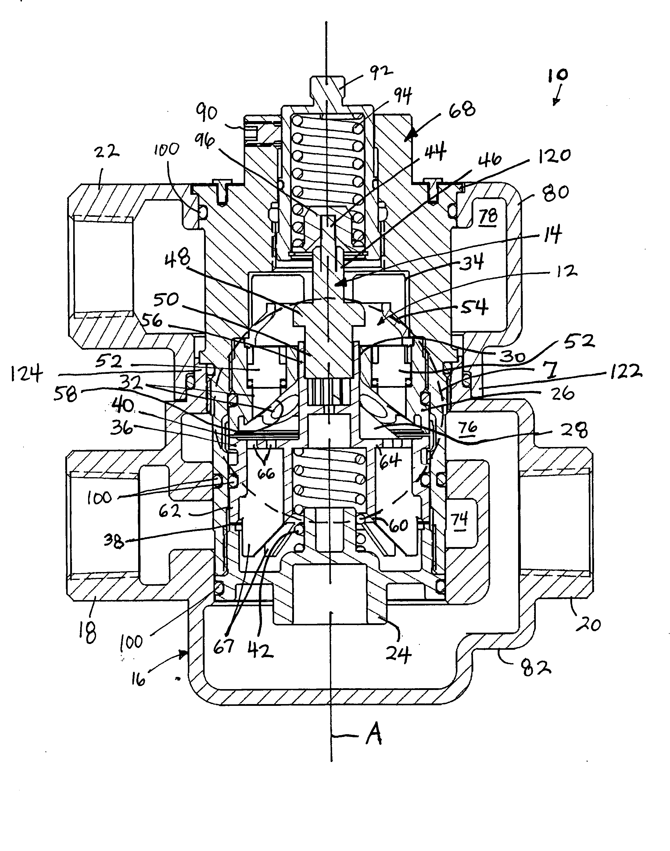
[0013] According to one aspect, the TMV further includes a cylindrical cartridge received within the housing. The first and the second seats, the plunger, and the thermal motor are coaxially mounted within the cartridge, and the mixing chamber and the sensing chamber are contained within and partially defined by the cartridge. The cartridge defines the outlet ports connecting the sensing chamber to the outlets of the housing, and further defines first inlet ports connecting the first inlet of the housing to the first valve opening and second inlet ports connecting the second inlet of the housing to the second valve opening. The cartridge allows easier assembly and disassembly of the TMV. In addition, the cartridge prevents the movable plunger from contacting the housing, and allows the more expensive housing to last longer while the less expensive plunger and valve seats are easily disassembled and replaced when worn.
[0014] According to an additional aspect, the housing of the TMV includes an upper portion defining the outlet secured to a lower portion defining the first and the second inlets, and the upper portion can be rotated about an axis of the housing with respect to the lower portion. This rotation feature is very helpful during installation of the TMV and allows the outlet to be oriented between 0° and 360° with respect to the inlets.

Problems solved by technology

Yet the TMV of the present disclosure does not allow excess flow to bypass the sensing chamber containing the thermal motor.

Method used


Image

  • Thermostatic mixing valve
  • Thermostatic mixing valve
  • Thermostatic mixing valve

Examples


Embodiment Construction

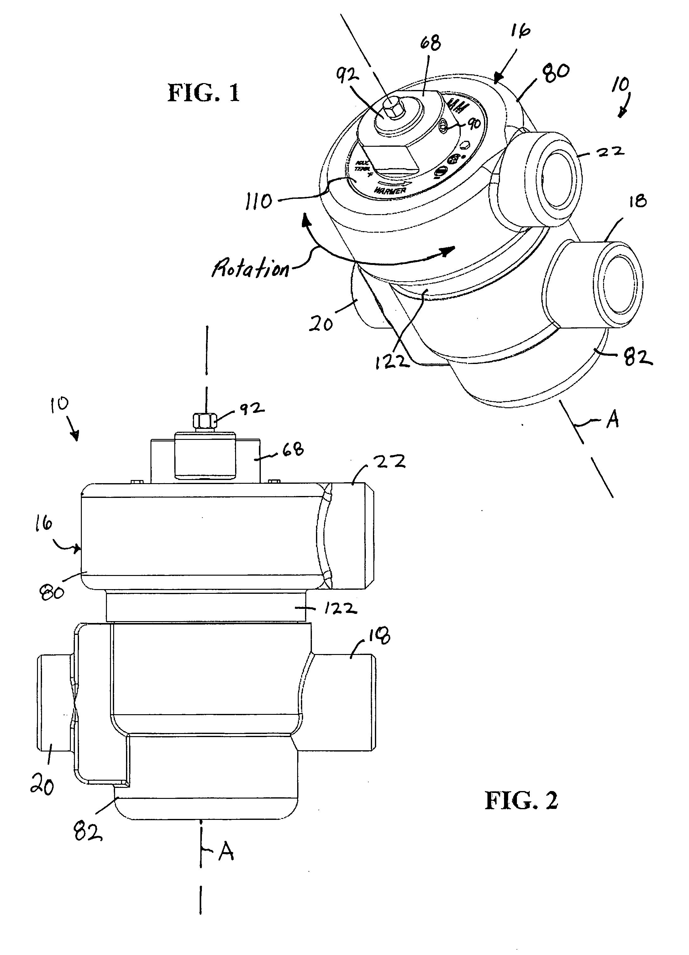
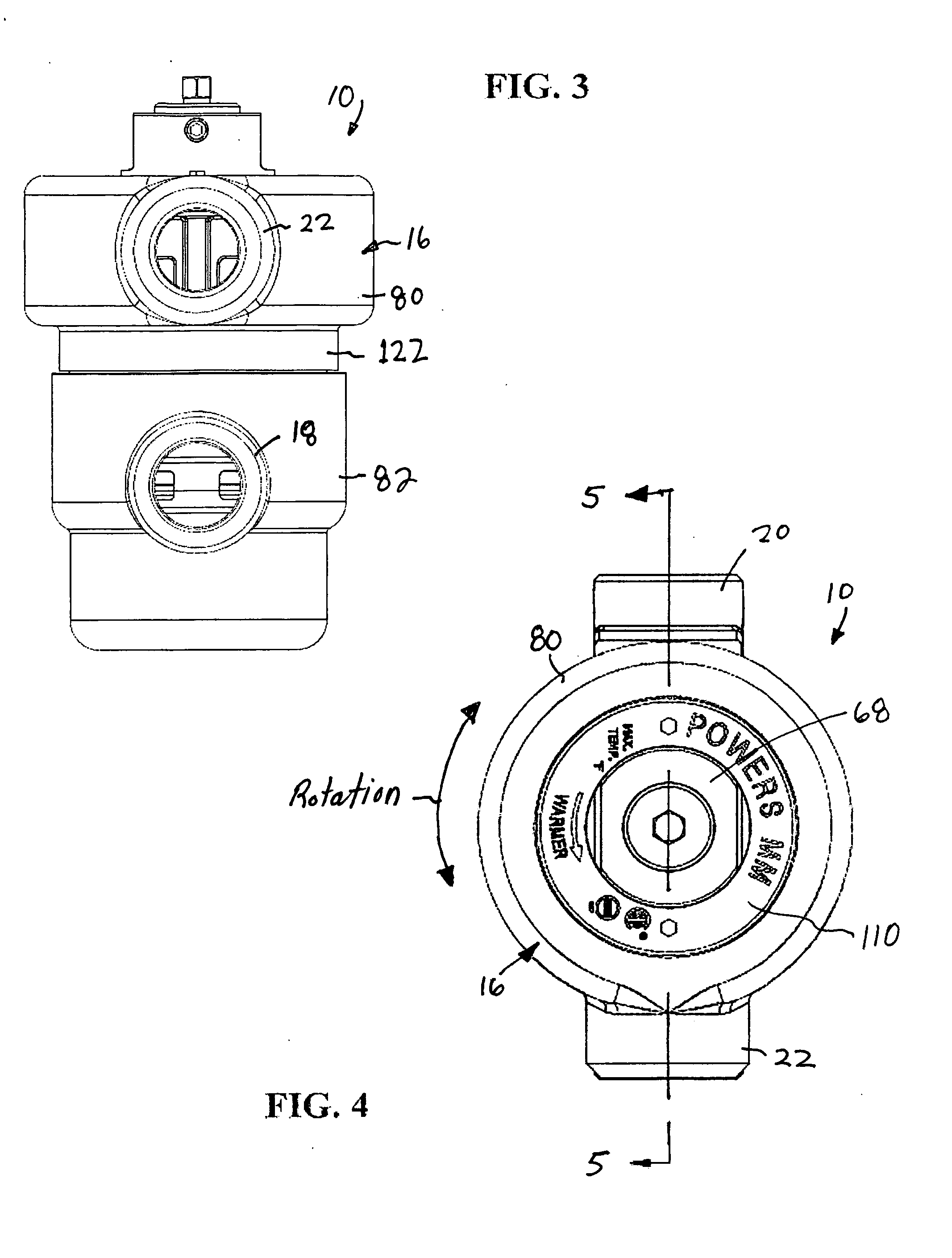
[0028] Referring to the figures, an exemplary embodiment of a new and improved thermostatic mixing valve (TMV) 10 according to the present disclosure is shown. Among other benefits, the new and improved TMV 10 of the present disclosure accommodates high-flow conditions as well as low-flow conditions. Yet the TMV 10 of the present disclosure does not allow excess flow to bypass a sensing chamber 12 containing a thermostat element 14 of the valve. Even at high flow rates, therefore, the TMV 10 accurately mixes hot and cold fluid.

[0029] The new and improved TMV 10 also includes a cartridge 68 that simplifies assembly of the TMV and the replacement of parts within the TMV. In addition, the new and improved TMV 10 includes a housing 16 having an upper portion 80 secured to a lower portion 82 by the cartridge 68. The upper portion 80 of the housing 16 can be rotated with respect to the lower portion 82 in order to allow an outlet 18 of the upper portion to be oriented between 0° and 360°...


PUM


Abstract

A thermostatic mixing valve (TMV) including a low-flow passageway and a high-flow passageway connecting a mixing chamber and a sensing chamber, and a check valve received in the high-flow passageway adapted to open and allow additional flow from the mixing chamber to the sensing chamber upon fluid flow through the valve rising to at least a predetermined high flow rate. The TMV accommodates a wide range of flows yet does not allow excess flow to bypass the sensing chamber which contains a thermal motor of the valve. Even at high flow rates, therefore, the TMV accurately mixes fluid.

Description

TECHNICAL FIELD OF THE DISCLOSURE [0001] The present disclosure generally relates to fluid control valves and, more particularly, to thermostatic mixing valves. Even more particularly, the present disclosure relates to a thermostatic mixing valve that is adapted to accommodate a wide range of flows yet does not allow excess flow to bypass a sensing chamber surrounding a thermostat element of the valve. BACKGROUND OF THE DISCLOSURE [0002] Thermostatic mixing valves (TMVs) are well established and serve to provide a fluid (e.g., water) supply at a desired temperature. TMVs, also referred to as temperature-activated mixing valves, have a temperature responsive thermostat element, or thermal motor, operatively coupled to a valve member controlling fluid flows through hot and cold inlet ports of the valve. The mixed fluids are caused to impinge upon the thermal motor, which in turn expands and contracts and controls the relative proportions of hot and cold fluids passing through the valv...

Claims


Application Information

Patent Timeline
Patent Type & Authority Applications(United States)
IPC IPC(8): G05D23/185
CPCG05D23/1346Y10T137/7925
Inventor GONCZE, ZOLTAN
Owner WATTS WATER TECH
Why Eureka
Try Eureka