
Method and apparatus for monitoring the condition of a battery by measuring its internal resistance

a technology of internal resistance and monitoring method, which is applied in the field of monitoring apparatus, can solve the problems of affecting the lifetime of the battery, the difference between the practical lifetime and the approximate lifetime of any particular battery, and the difference is sometimes very larg

Inactive Publication Date: 2007-08-23
BPPOWER
View PDF32 Cites 85 Cited by
  • Summary
  • Abstract
  • Description
  • Claims
  • Application Information

AI Technical Summary

Benefits of technology

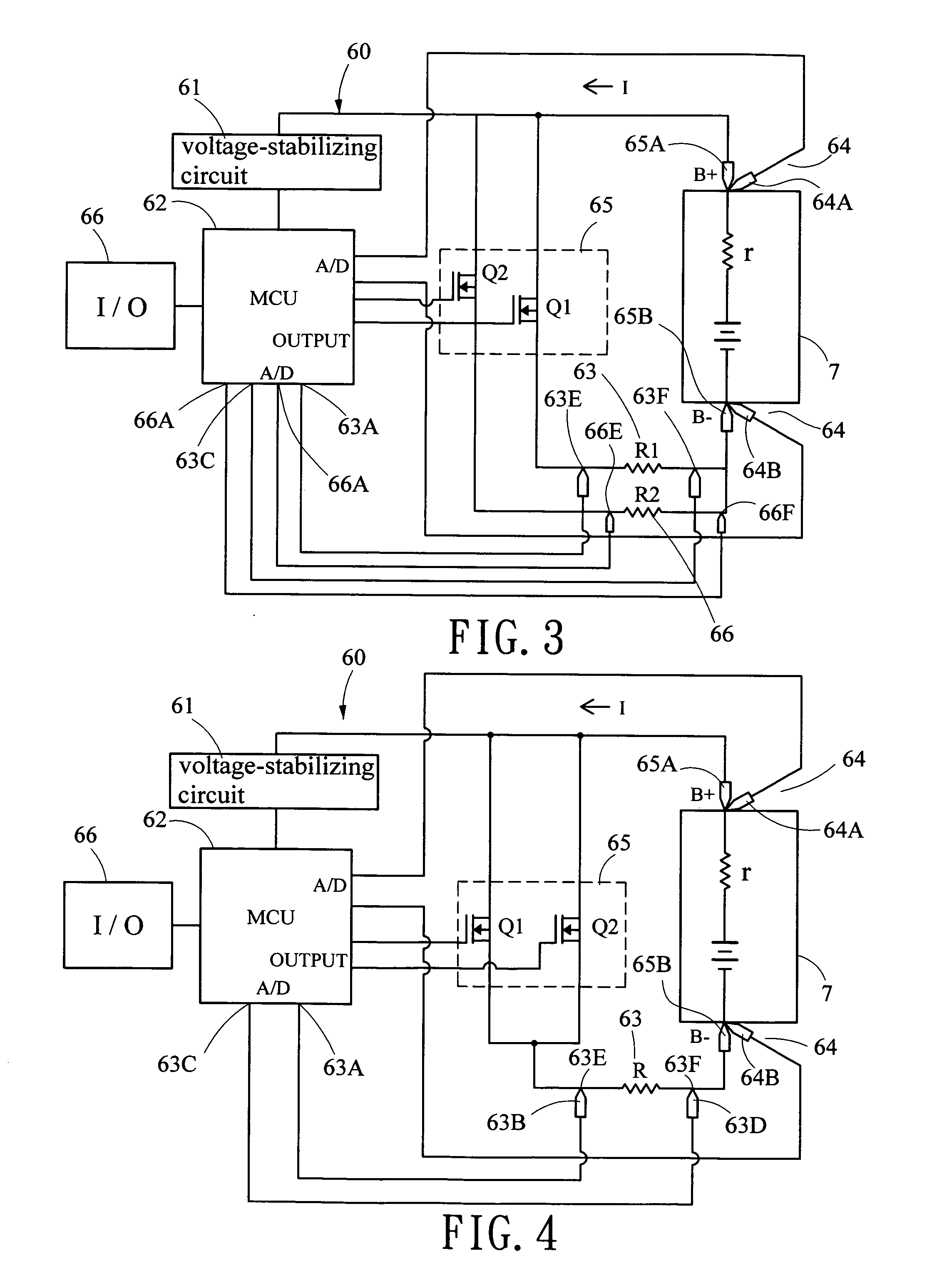
[0023] It is an object of the present invention to provide an apparatus of long-term monitoring or short time test at two terminals of the battery in a relatively transient sampling time with a transient large current by consuming a minimum amount of electric power thereof such that a warning can be displayed for the driver via an I / O operation if the power is lower than a predetermined level during running of the engine or prior to starting the engine.
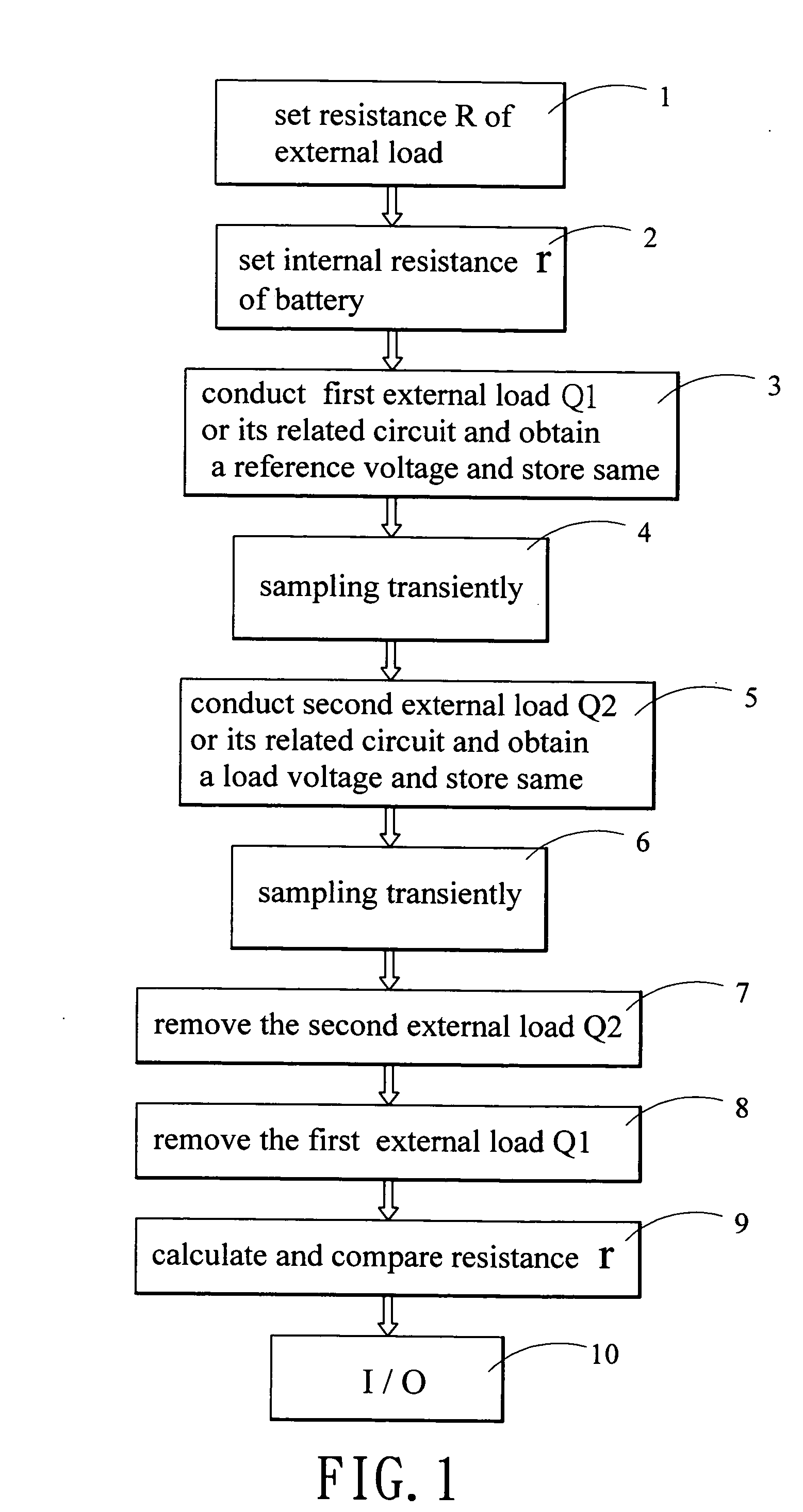
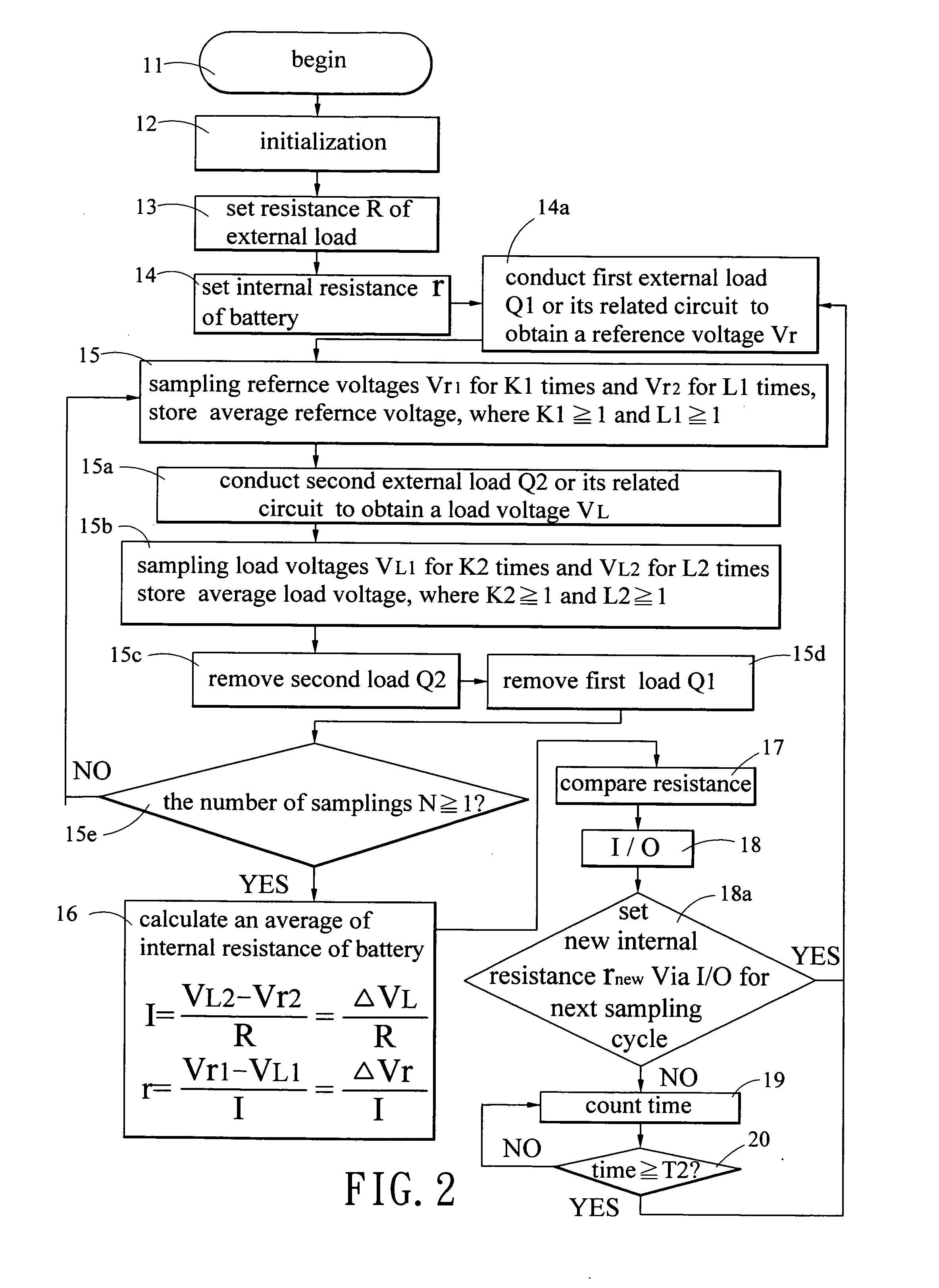
[0024] It is a further object of the present invention to provide a method of monitoring electric power of a battery, comprising the steps of (1) setting a resistance of an external load based on battery type and an internal resistance of the battery to be measured; (2) setting an internal resistance of the battery to be measured; (3) transiently sampling at two terminals of the battery to be measured with a transient large current supplied from a conducted first power transistor for a plurality of first and second times so as to obtain an average of each group of first and second sampled reference voltages; (4) transiently sampling at two terminals of the battery to be measured with a transient large current supplied from a conducted second power transistor for a plurality of first and second times so as to obtain an average of each group of first and second sampled load voltages; (5) removing the first and second power transistors; (6) dividing a difference between the second sampled load voltage and the second sampled reference voltage by the resistance of the external load to obtain a transient large current of the battery; (7) dividing a difference between the average first sampled reference voltage and the average first sampled load voltage by the transient large current of the battery to obtain the internal resistance of the battery; (8) comparing the obtained internal resistance of the battery to be measured with a predetermined warning value of the internal resistance of the battery so as to determine whether the former is equal to or larger than the predetermined warning value or not; and (9) issuing a warning through an I / O if the determination in step (8) is affirmative. By utilizing this method, it is possible of enabling a driver to know the actual electric power capacity of the battery in substantially real time.

Problems solved by technology

However, factors such as ambient temperature, charging conditions and time, and load discharge all can adversely affect the lifetime of the battery.
Thus, there is difference between the practical lifetime and the approximate lifetime of any particular battery and the difference is sometimes very large.
Hence, in practice, there is no way for a driver (or even an experienced one) to know the electric power level of the battery prior to starting the engine.
However, the test device is somewhat bulky, thus prohibiting it from being carried by the motor vehicle.
Alternatively, the battery may be already damaged but the driver is not aware before next start even it is successful in a particular start.
This is not desirable and may even be dangerous since the driver may park his / her car in a remote area, mountain, or desert.
But power measurement of the battery may also consume the electric power of the battery.
Hence, a frequent power measurements is not desirable.
However, a value of the floating voltage V0 itself is not stable as it will be affected by intermittently charging on the battery or up and down variation of load at two terminals of the battery or ageing of the battery.
U.S. Pat. No. 6,424,157 refers to the difficulty of measuring battery SOC from open-circuit voltage (OCV) because this requires that everything be disconnected.

Method used


Image

  • Method and apparatus for monitoring the condition of a battery by measuring its internal resistance
  • Method and apparatus for monitoring the condition of a battery by measuring its internal resistance
  • Method and apparatus for monitoring the condition of a battery by measuring its internal resistance

Examples


Embodiment Construction

[0040] Referring to FIGS. 1 and 8, a process of monitoring the electric power of a battery (e.g., one installed in an automobile) according to the invention is illustrated.

[0041] In step 1, the resistance R of an external load is set, that is selected from values between 25uΩ to 5000mΩ optionally by means of using an amplifier based on battery type and an internal resistance of the battery to be measured.

[0042] In step 2, the predetermined value to which the internal resistance r of the battery will be compared is selected from the range of 0.001 Ω to 1.5Ω based on the battery type. An appropriate setting depends on applications so as to provide a predetermined value, a warning range, or one of a plurality of predetermined warning values for multiple stages of warning before the end of discharging (see FIG. 8).

[0043] In step 3, a first power transistor Q1 or its related circuit is controlled to conduct as a first external load. Obtain a plurality of reference voltages thereof and...


PUM

PropertyMeasurementUnit
internal resistanceaaaaaaaaaa
resistanceaaaaaaaaaa
currentaaaaaaaaaa

Abstract

A method comprises coupling a first power transistor as a first external load in series with the battery, coupling a second power transistor as a second external load in series with the battery, conducting each power transistor to supply a transient large current to the battery for sampling a group of sampled reference voltages and sampled load voltages in a very transient sampling time for a plurality of times and thus obtaining an internal resistance of the battery. The internal resistance of the battery can then be compared with a predetermined warning value thereof so as to determine whether the former is equal to or larger than the warning value or not, and issuing a warning through an I / O if the determination is affirmative. The invention enables a driver to correctly know the actual condition of the battery in substantially real time while consuming a minimum amount of power.

Description

BACKGROUND OF THE INVENTION [0001] 1. Field of the Invention [0002] The present invention relates to monitoring apparatus and more particularly to a method of monitoring the electric power of a battery by measuring the internal resistance of the battery by means of conducting a first power transistor as a first external load to obtain a reference voltage and then conducting second power transistor as second external load to obtain a load voltage and comparing the internal resistance of the battery with a predetermined warning value thereof such that a warning can be displayed if the power is lower than a predetermined level prior to starting the engine. The present invention further particularly relates to such a monitoring apparatus. [0003] 2. Description of Related Art [0004] It is known that a driver has to start the engine of a motor vehicle before driving it. Also, for successfully starting the engine, there must be sufficient electric power stored in the battery. Typically, a ...

Claims


Application Information

Patent Timeline
Patent Type & Authority Applications(United States)
IPC IPC(8): G01N27/416
CPCG01R31/3648G01R31/3647G01R31/389G01R31/36
Inventor HUANG, YUNG-SHENG
Owner BPPOWER
Learn More