
Liquid crystal display device and driving method thereof

a technology of liquid crystal display and driving method, which is applied in the direction of instruments, electric digital data processing, computing, etc., can solve the problems of gate drive signal undesirably distorted, signal line resistance increase, and deterioration of picture quality of lcd, so as to prevent brightness differences

Active Publication Date: 2007-08-23
LG DISPLAY CO LTD
View PDF16 Cites 5 Cited by
  • Summary
  • Abstract
  • Description
  • Claims
  • Application Information

AI Technical Summary

Benefits of technology

[0030] An advantage of the present invention provides a liquid crystal display capable of preventing a difference in brightness from being generated between horizontal line blocks and a driving method thereof.

Problems solved by technology

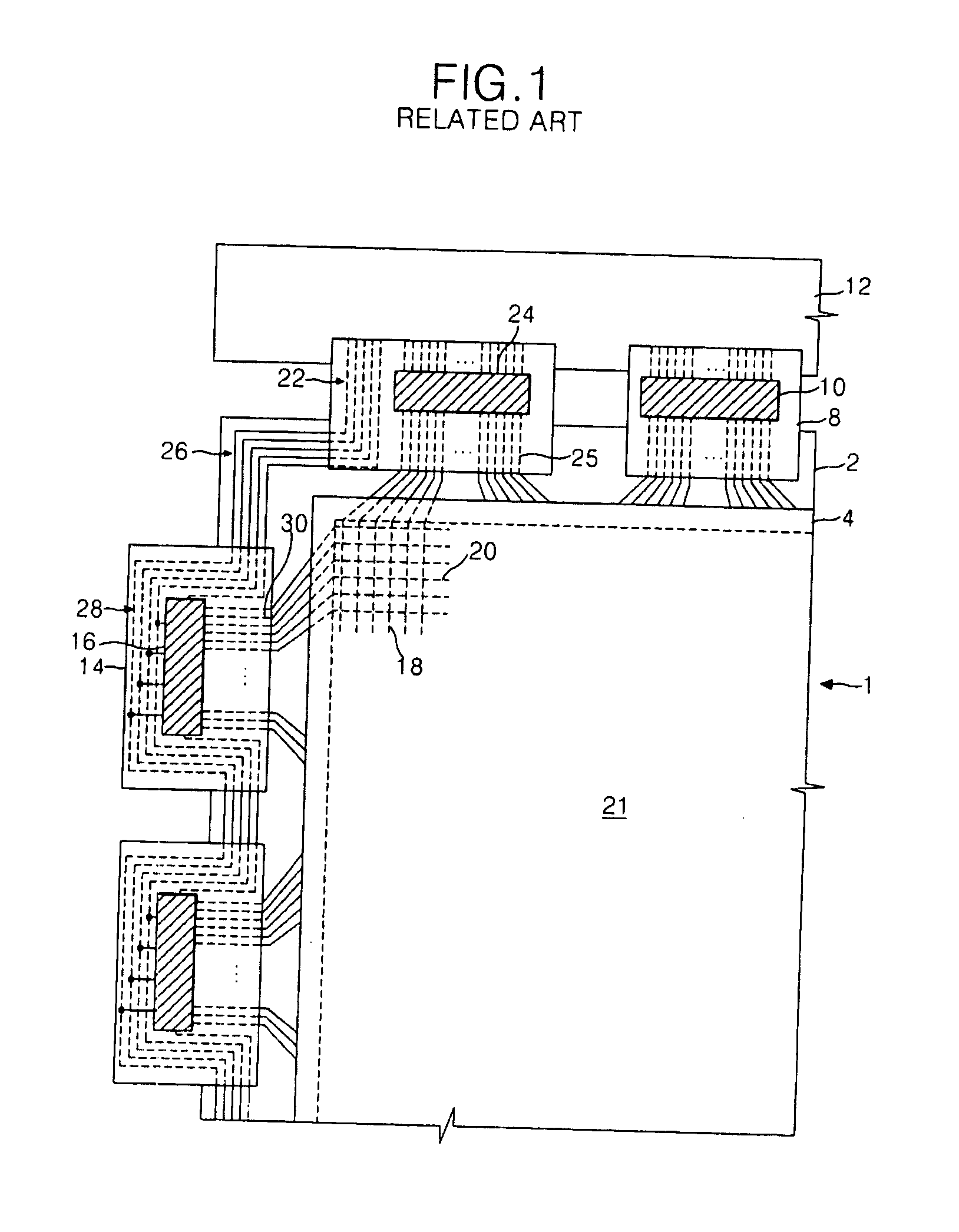
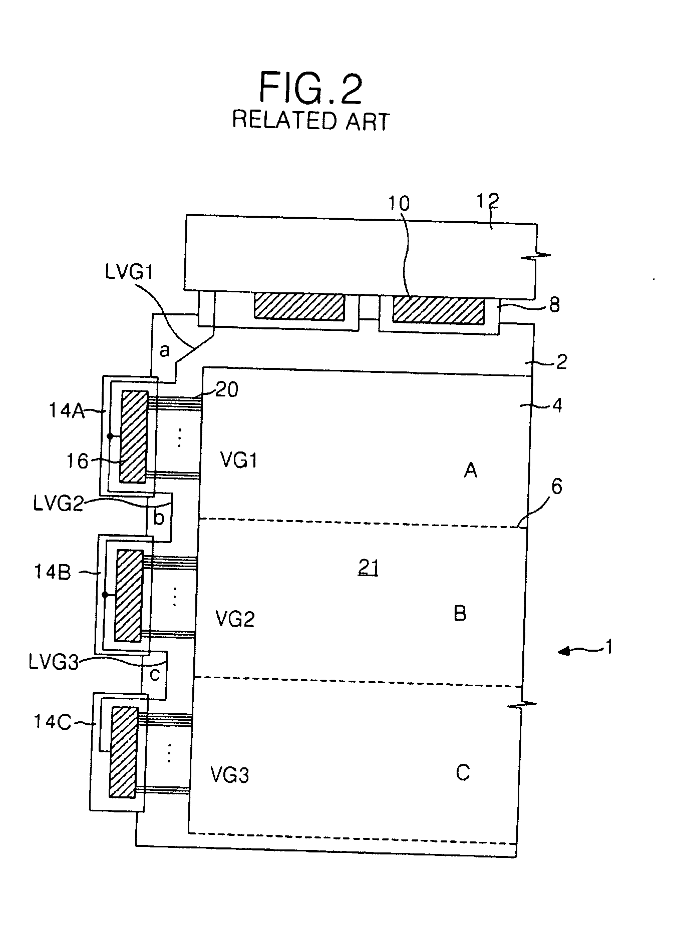
Accordingly, as the distance from the data PCB 12 increases, the resistance of the signal line increases to the point that the gate drive signals become undesirably distorted.
This causes the picture display area 21 to appear divided, thereby deteriorating a picture quality of the LCD.
Accordingly, it becomes not only difficult to provide a plurality of LOG type signal lines, but there is a physical limit as to how large the cross section of a transmission line can be initially formed.

Method used


Image

  • Liquid crystal display device and driving method thereof
  • Liquid crystal display device and driving method thereof
  • Liquid crystal display device and driving method thereof

Examples


Embodiment Construction

[0059] Reference will now be made in detail to embodiments of the present invention, examples of which are illustrated in the accompanying drawings.

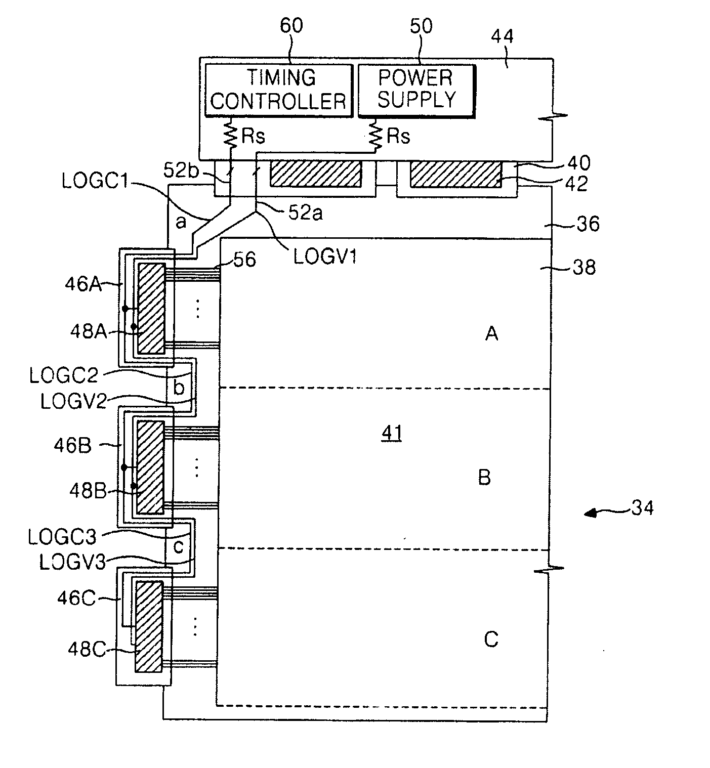
[0060]FIG. 3 illustrates a plan view of an LOG LCD according to a first aspect of the present invention.

[0061] Referring to FIG. 3, the liquid crystal display (LCD) according to the first aspect of the present invention may, for example, include an LCD panel 34; a plurality of data TCPs 40 connected between a first side of the LCD panel 34 and a data PCB 44; first to third gate TCPs 46A to 46C, respectively, connected to a second side of the LCD panel 34; a plurality of data driver ICs 42 mounted onto respective ones of the TCPs 40; first to third gate driver ICs 48A to 48C, respectively, mounted onto respective ones of the first to third gate TCPs 46A to 46C; a power supply 50 for generating drive voltages and for applying the generated drive voltage to the gate driver ICs 48 and the data driver ICs 42, and a timing controller 60 for ...


PUM

PropertyMeasurementUnit
resistanceaaaaaaaaaa
voltageaaaaaaaaaa

Abstract

A liquid crystal display and a method of driving the same is capable of for preventing a difference in brightness from occurring between horizontal line blocks. A liquid crystal display includes a liquid crystal display panel having liquid crystal cells arranged in a matrix pattern; at least one integrated circuit for driving the liquid crystal display panel; a supply line commonly connected to the at least one integrated circuit for applying drive signals to the at least one integrated circuit; and a signal-limiting part formed at an input terminal of the supply line, wherein the supply line has a higher resistance than the sum of the line resistances of the entire supply line.

Description

[0001] This application claims the benefit of Korean Patent Application No. P2002-62429, filed on Oct. 14, 2002, which is hereby incorporated by reference for all purposes as if fully set forth herein. BACKGROUND OF THE INVENTION [0002] 1. Field of the Invention [0003] The present invention relates to liquid crystal displays, and more particularly to liquid crystal displays capable of preventing a difference in brightness from being generated between horizontal line blocks and a driving method thereof. [0004] 2. Description of the Related Art [0005] Generally, liquid crystal displays (LCDs) control light transmittance characteristics liquid crystal material using electric fields to display pictures. Accordingly, LCDs typically include a LCD panel having a plurality of liquid crystal cells arranged in a matrix pattern and a drive circuit for driving the LCD panel. [0006] The LCD panel includes a plurality of gate lines and a plurality of data lines arranged so as to cross one another...

Claims


Application Information

Patent Timeline
Patent Type & Authority Applications(United States)
IPC IPC(8): G09G3/36G02F1/1345G02F1/133G09G3/20
CPCG02F1/13452G09G3/3611G09G3/3614G09G3/3659G09G3/3677G09G2320/0233G09G2300/0426G09G2300/0876G09G2320/0219G09G2320/0223G09G3/3696G02F1/133
Inventor SONG, SANG MOOKIM, SANG RAEPARK, JAE HONG
Owner LG DISPLAY CO LTD
Learn More