
Large Screen Digital Image Projector

a digital image and projector technology, applied in the field of large-screen digital projection, can solve the problem of not allowing a uniform brightness of the three images, and achieve the effect of uniform brightness and high quality

Inactive Publication Date: 2007-08-23
THOMSON LICENSING SA
View PDF24 Cites 18 Cited by
  • Summary
  • Abstract
  • Description
  • Claims
  • Application Information

AI Technical Summary

Benefits of technology

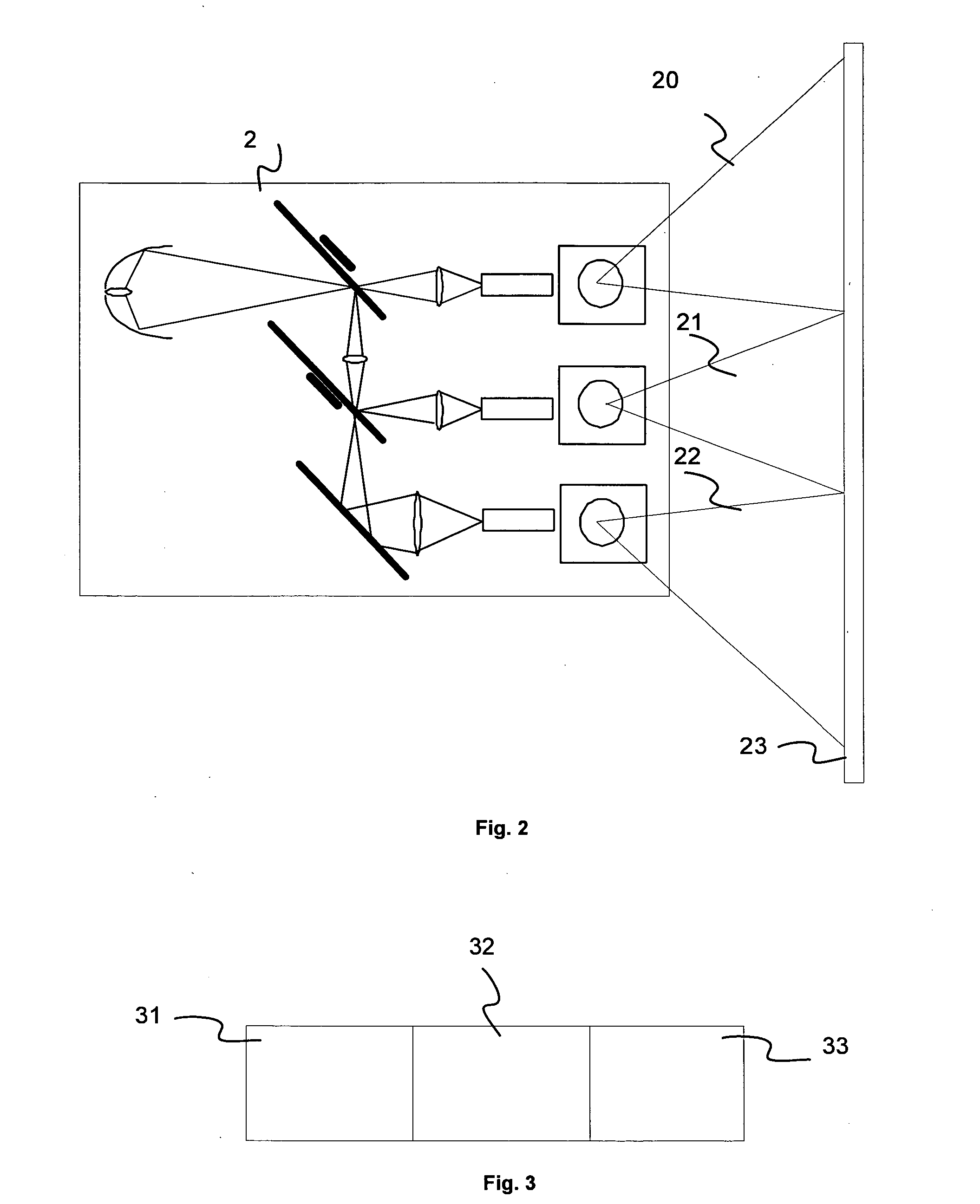
[0004] More particularly, the objective of the invention is to allow a digital image projection of high quality on a large-sized screen, with notably a uniform brightness.

Problems solved by technology

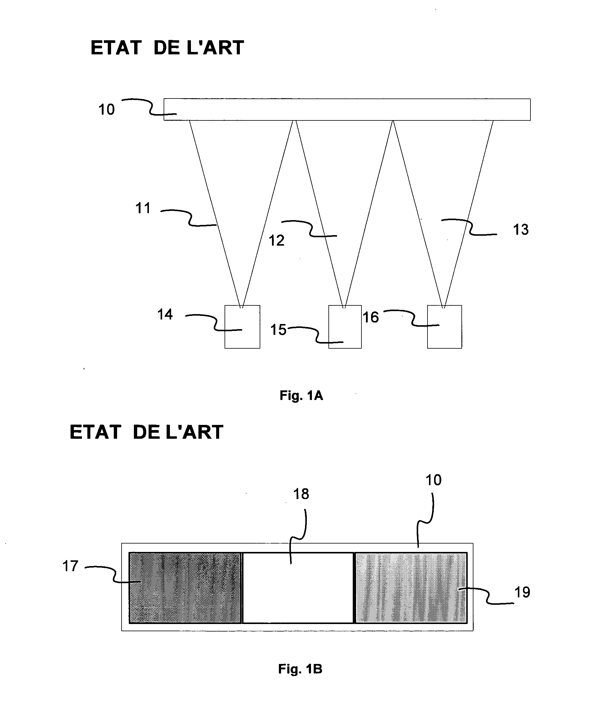
This technique has the drawback of not allowing a uniform brightness of the three images 17 to 19, especially when the lamps of the projectors 14 to 16 begin to age.

Method used


Image

  • Large Screen Digital Image Projector
  • Large Screen Digital Image Projector
  • Large Screen Digital Image Projector

Examples


first embodiment

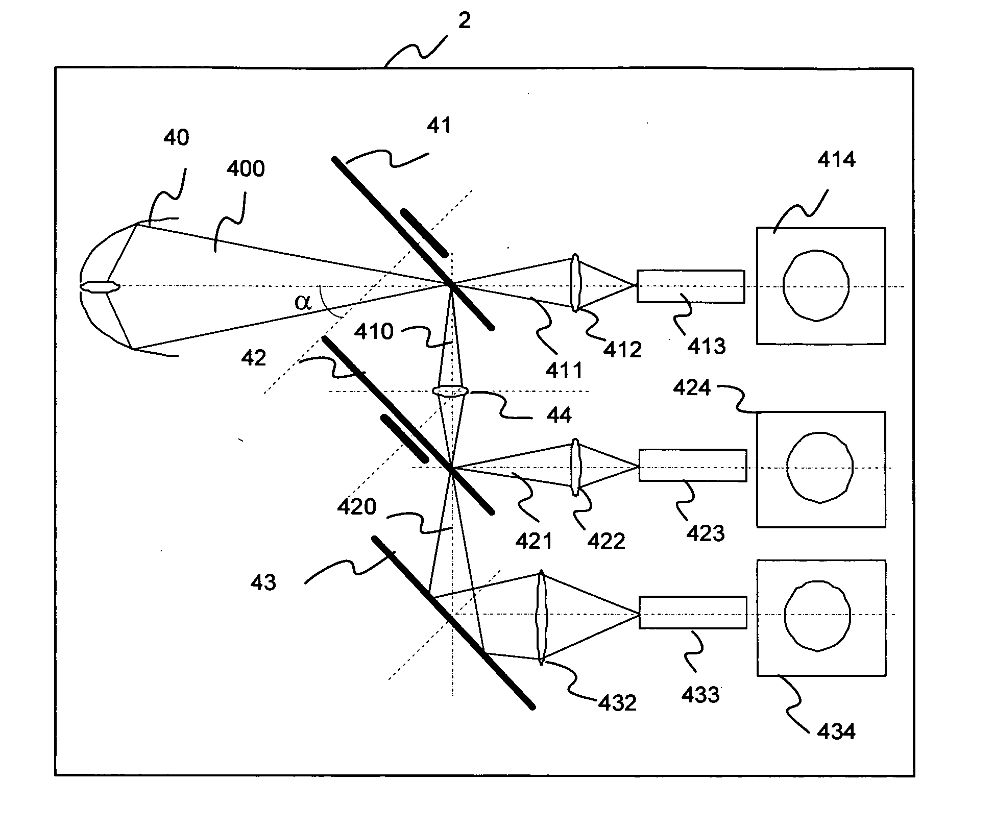
[0087] the separation means 78 are of the polarization means type, preferably of the grating polarizer type (for example Moxtek ®) which can be inclined between 25° and 70° with respect to the axis of the beam 400. According to one variant, the polarizer is of the PBS (Polarization Beam Splitter) type. In this case, the polarizer is inclined with an angle close to 45° with respect to the axis of the beam 400.

second embodiment

[0088] the separation means 78 are of the semi-transparent mirror type. Preferably, the mirror comprises two parts, that are respectively reflecting and transparent, which can be more or less interlaced (for example, ‘dot mirrors’), the reflecting part representing half of the surface area of the mirror. According to one variant, the mirror comprises a special treatment that allows 50% of the incident flux to be reflected and the remaining 50% to be transmitted. Thus, the beam 400 is divided into two beams 70 and 81 of equal, or very similar, brightness.

[0089] The second imaging assembly 77 is very similar to the first imaging assembly 76.

[0090] It notably comprises: [0091] two colored wheels 71 and 72 (which replace the wheels 41 and 42); [0092] a focusing lens 74 (replacing the lens 44); [0093] a mirror 73 (replacing the mirror 43) that reflects the beam 81 toward the wheel 71; [0094] three focusing lenses 712, 722 and 732 (replacing the lenses 412, 422 and 432); [0095] three li...


PUM


Abstract

The invention relates to a projection system comprising: a polychromatic light source and at least one imaging assembly illuminated by an associated polychromatic illumination beam, and comprising: two separate colored wheels respectively called first and second colored wheel; and three separate imagers respectively called first, second and third imagers. At least one part of the polychromatic beam, called first source beam, illuminating the first colored wheel which separates said source beam into a first monochromatic beam and into a two-tone beam, said first monochromatic beam illuminating the first imager and said two-tone beam being transmitted towards the second colored wheel. The second colored wheel being illuminated by said two-tone beam and separating said two-tone beam into second and third monochromatic beams, respectively illuminating said second and third imagers respectively.

Description

1. FIELD OF THE INVENTION [0001] The present invention relates to the projection of images and, more precisely, to large screen digital projection, for example of the movie theatre type. 2. TECHNOLOGICAL BACKROUND [0002] According to the prior art, in order to project a very large size of image, since a conventional projector cannot project a sufficiently bright image when a very large screen is used, several projectors are implemented such as is illustrated in FIG. 1A. Thus, digital projectors 14 to 16 each project an image onto the same screen 10. The transmitted beams 11 to 13 associated with each of the projectors 14 to 16 are adjacent to one another. Electronic processing means, that are relatively complex, allow the separation between the three projected images to be rendered invisible, as is illustrated in FIG. 1B. This technique has the drawback of not allowing a uniform brightness of the three images 17 to 19, especially when the lamps of the projectors 14 to 16 begin to ag...

Claims


Application Information

Patent Timeline
Patent Type & Authority Applications(United States)
IPC IPC(8): G03B21/26H04N5/74H04N9/12H04N9/31
CPCH04N9/3197H04N9/3147G03B21/00G03B21/14H04N9/12H04N9/31
Inventor DRAZIC, VALTERSARAYEDDINE, KHALED
Owner THOMSON LICENSING SA
Learn More