Plug-In Network Appliance

a network appliance and plug-in technology, applied in the field of communication, can solve the problems of bulky devices, add to the cost,

Active Publication Date: 2007-08-23
CENTRAK
View PDF34 Cites 97 Cited by
  • Summary
  • Abstract
  • Description
  • Claims
  • Application Information

AI Technical Summary

Problems solved by technology

However, in many instances, due to limitations in battery life, it is often convenient to use a powered device within a network.
This adds to the cost, and bulkiness of the device.

Method used


Image

  • Plug-In Network Appliance
  • Plug-In Network Appliance
  • Plug-In Network Appliance

Examples


Embodiment Construction

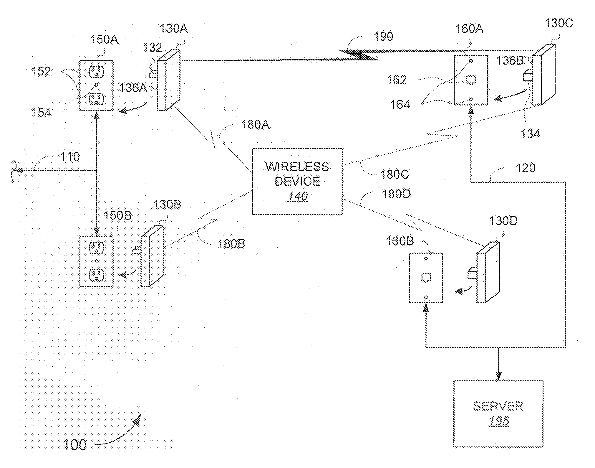
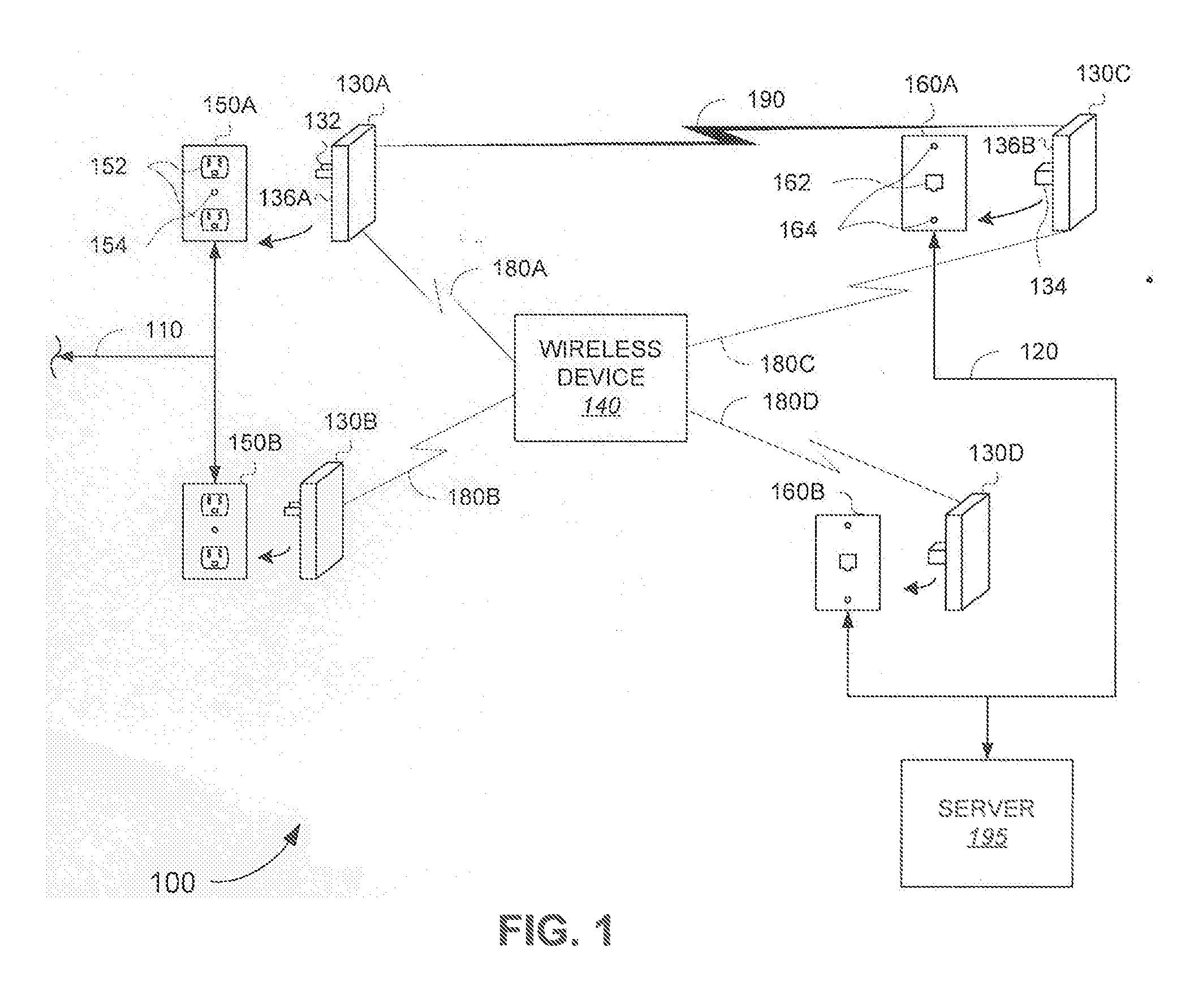
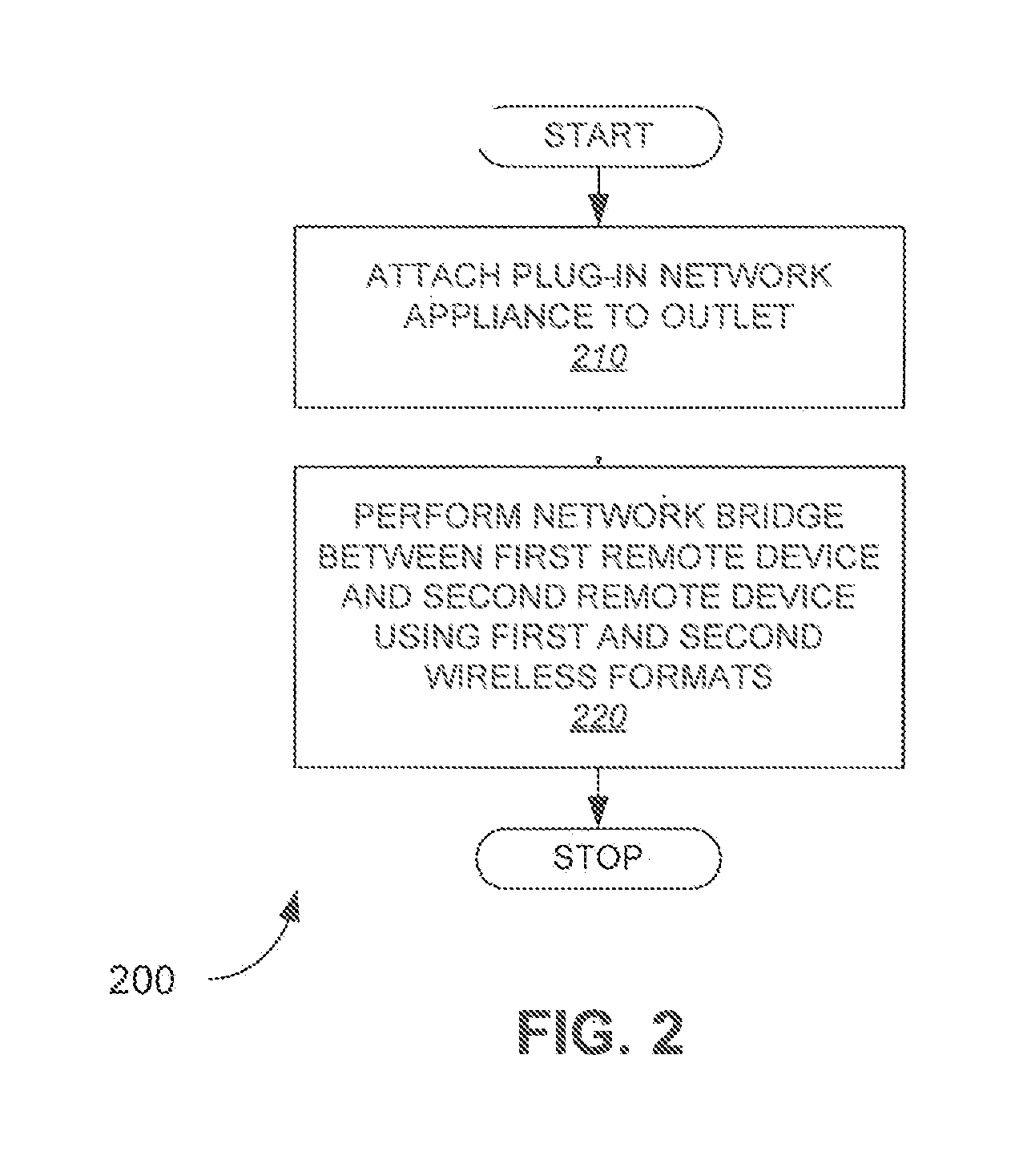
[0037] One or more exemplary embodiments described herein are set forth in the context of a wireless data communication system. While use within this context is advantageous, different embodiments of the invention may be incorporated in different environments or configurations. In general, the various systems described herein may be formed using software-controlled processors, integrated circuits, or discrete logic. The data, instructions, commands, information, signals, symbols, and chips that may be referenced throughout the application are advantageously represented by voltages, currents, electromagnetic waves, magnetic fields or particles, optical fields or particles, or a combination thereof. In addition, the blocks shown in each block diagram may represent hardware or method steps. The word “exemplary” is used herein to mean “serving as an example, instance, or illustration.” Any embodiment described herein as “exemplary” is not necessarily to be construed as preferred or adva...


PUM


Abstract

A plug-in network appliance is disclosed. In one aspect, a network appliance performs a bridge between two wireless communication formats. In another aspect, a network appliance is deployed to perform position location services. In another aspect, a mesh network comprising one or more network appliances is deployed. A mesh network comprising one or more network appliances may be deployed to perform position location services. A plug-in form factor is described. A network appliance may convert power received from a plug in a first format to power in a second format for powering various components. A network appliance may connect with a wireless network and/or a network connected through a plug. A plug-in network appliance may connect to a weight-bearing outlet. Various other aspects are also presented.

Description

CROSS REFERENCES TO RELATED APPLICATIONS [0001] The Present application is a continuation application of U.S. patent application Ser. No. 11 / 008,802, filed on Dec. 8, 2004, which claims priority to U.S. Provisional Application No. 60 / 528,052, filed Dec. 9, 2003, U.S. Provisional Application No. 60 / 572,690, filed May 19, 2004, and U.S. patent application Ser. No. 10 / 968,814, filed Oct. 18, 2004.STATEMENT REGARDING FEDERALLY SPONSORED RESEARCH OR DEVELOPMENT [0002] Not Applicable BACKGROUND OF THE INVENTION [0003] 1. Field of the Invention [0004] The present invention relates generally communications, and more specifically to a plug-in network appliance. [0005] 2. Description of the Related Art [0006] There is a well-established demand for wireless networking devices. Connectivity is desired without the need for installing and maintaining various wires and cables, and the convenience of fewer such wires within the home, office, or other facility. Various wireless networking components...

Claims


Application Information

Patent Timeline
Patent Type & Authority Applications(United States)
IPC IPC(8): H04M1/00H04B3/54H04B7/14H04B7/15H04LH04L12/28H04W84/12
CPCH04B3/542H04B2203/5441H04L12/2803H04W84/12H04L2012/2841H04L2012/2843H04L12/2832Y02D30/70
Inventor SMITH, DEREK M.ADAMS, JAMES D.NIERENBERG, NICOLAS C.BAKER, JOSEPH C.
Owner CENTRAK
Why Eureka
Try Eureka