Differential device

a technology of differential devices and components, applied in the direction of magnetically actuated clutches, packaging, gearing, etc., can solve the problems of complex structure, maintenance and repair, and inaccessibility to these elements

Inactive Publication Date: 2007-08-23
GKN DRIVELINE TORQUE TECHNOLOGY KK
View PDF11 Cites 45 Cited by
  • Summary
  • Abstract
  • Description
  • Claims
  • Application Information

AI Technical Summary

Problems solved by technology

Installing the clutch and these means in a casing of the differential leads to complexity of a structure and inacc

Method used


Image

  • Differential device
  • Differential device
  • Differential device

Examples


Embodiment Construction

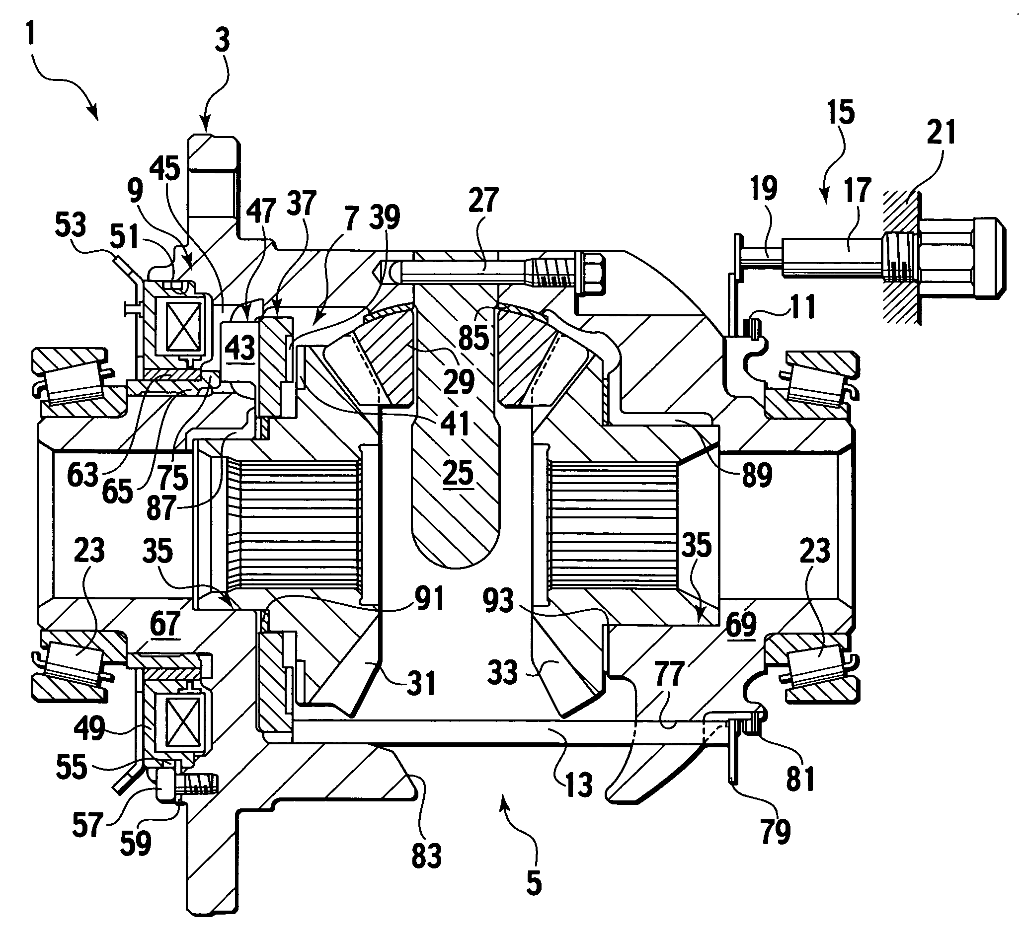
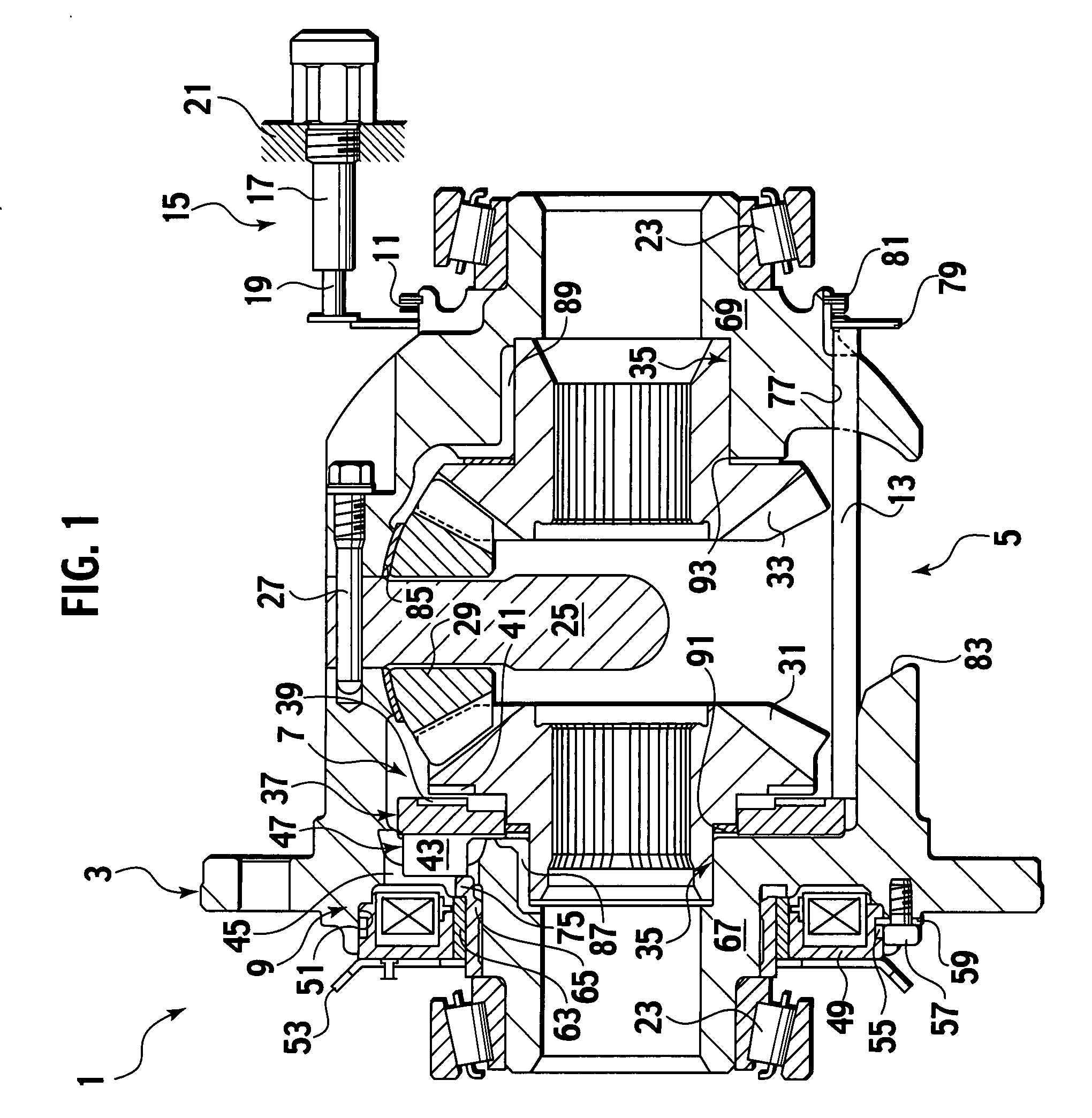
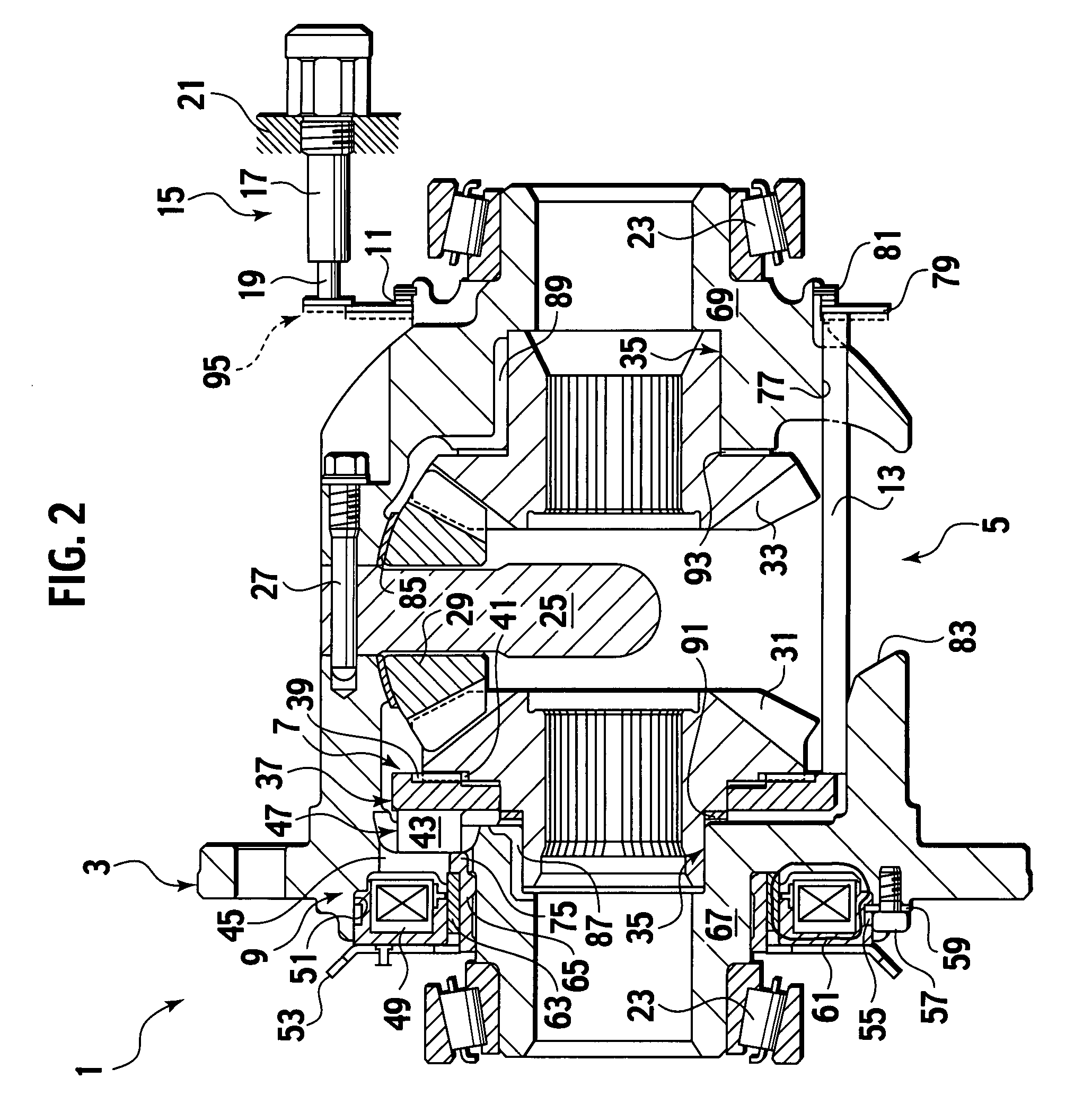
[0016]An embodiment of the present invention will be described hereinafter with reference to the appended drawings. Throughout the specification, claims and the drawings, some terms are specially defined in accordance with the following definitions unless any other particular explanations are given. An axial direction is defined as a direction along an axis of a differential device, which is generally correspondent to lateral directions of FIGS. 1-3. Ends are defined as extremes in the axial direction. An end face is defined as a face visible in a projection drawn along the axial direction.

[0017]FIGS. 1-7 illustrates a differential device 1 in accordance with the embodiment of the present invention. In the following description, the right and the left are correspondent to those of FIGS. 1-3.

[0018]Referring to FIGS. 1 and 2, the differential device 1 is provided with a differential gear set 5 of, but not limited to, a bevel gear type so as to differentially transmit a driving force o...


PUM


Abstract

A differential device is provided with a case being capable of rotation around a rotation axis; a differential gear set housed in and drivingly coupled to the case, which includes first and second output gears and is configured to differentially transmit the rotation of the case to the first and second output gears; a clutch configured to controllably limit and free a differential motion between the first and second output gears, which is housed in the case; an actuator configured to actuate the clutch; and a notifying member configured to notify whether the differential motion is limited or freed to an exterior of the case.

Description

CROSS-REFERENCE TO RELATED APPLICATIONS[0001]This application is based upon and claims the benefit of priority from the prior Japanese Patent Application No. 2006-042853 (filed Feb. 20, 2006); the entire contents of which are incorporated herein by reference.BACKGROUND OF THE INVENTION[0002]1. Field of the Invention[0003]The present invention relates to a differential device applied to conveyance means such as automobiles, differential motion of which is controllable and detectable from the exterior thereof.[0004]2. Description of the Related Art[0005]As is known, an automobile is equipped with a differential to distribute a driving force of an engine to right and left output axles. The differential allows a differential motion between the axles and hence right and left wheels can maintain traction with the road while the automobile is turning.[0006]To provide a driver with operability for temporary lock of the differential motion, a so-called “Lock-up Differential” is used. The loc...

Claims


Application Information

Patent Timeline
IPC IPC(8): F16H48/06F16D27/118F16H48/08F16H48/24F16H48/38
CPCF16H48/08F16H48/24F16H2048/346F16H48/34F16H2048/204F16H48/30
Inventor FUSEGI, MASAAKI
Owner GKN DRIVELINE TORQUE TECHNOLOGY KK
Why Eureka
Try Eureka