Default device of actuator for variable lift valve operating mechanism

Inactive Publication Date: 2007-08-30
HONDA MOTOR CO LTD
View PDF5 Cites 2 Cited by
  • Summary
  • Abstract
  • Description
  • Claims
  • Application Information

AI Technical Summary

Benefits of technology

[0024] With the above described configuration, at least part of the driven gear overlaps the pair of rod-shaped spring guides, and is placed between the

Problems solved by technology

In order to obtain a sufficient default load with the resilient force of the coil spring, there is a need for increasing the size of the coil spring o

Method used


Image

  • Default device of actuator for variable lift valve operating mechanism
  • Default device of actuator for variable lift valve operating mechanism
  • Default device of actuator for variable lift valve operating mechanism

Examples


Example

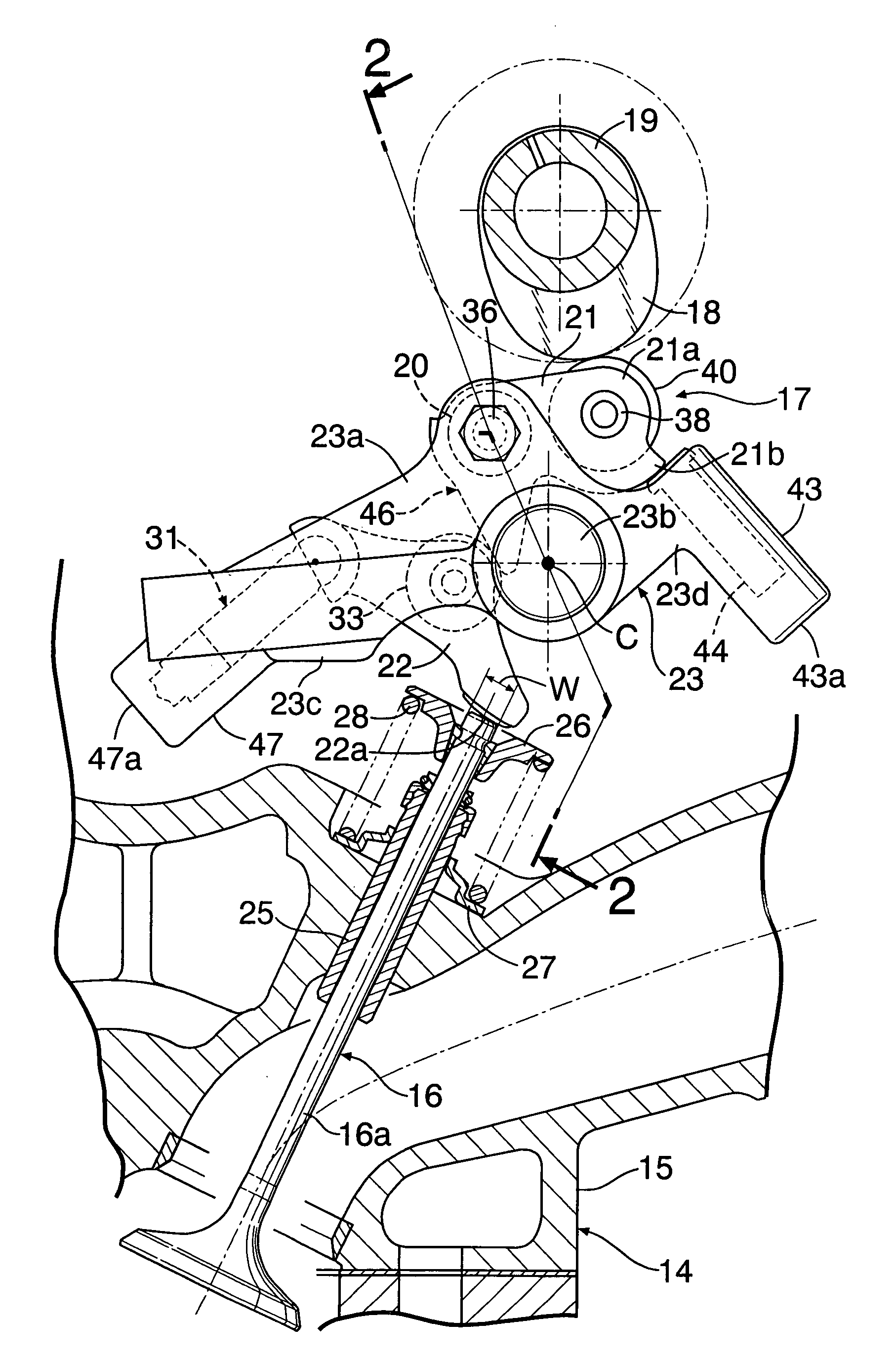
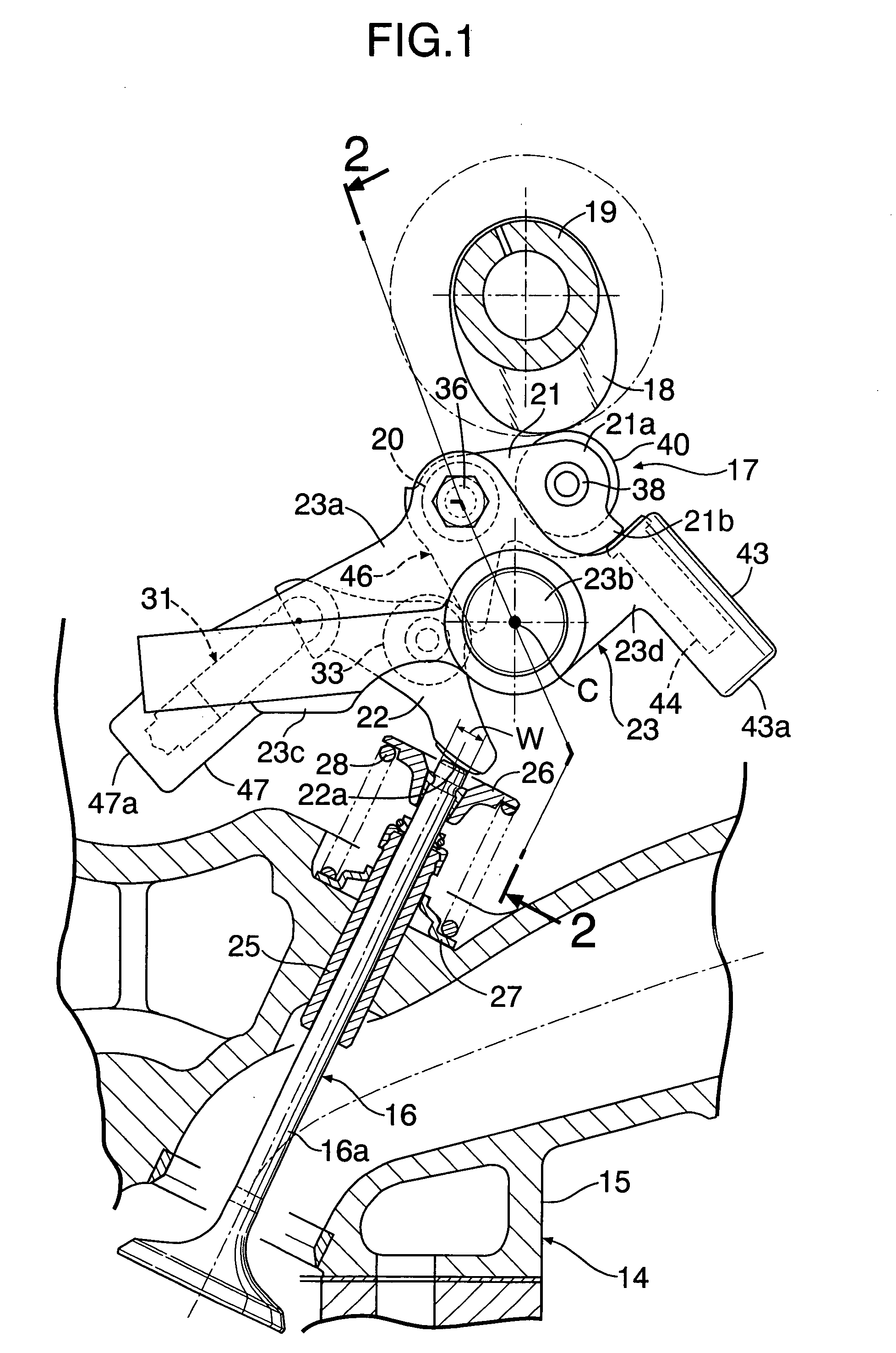
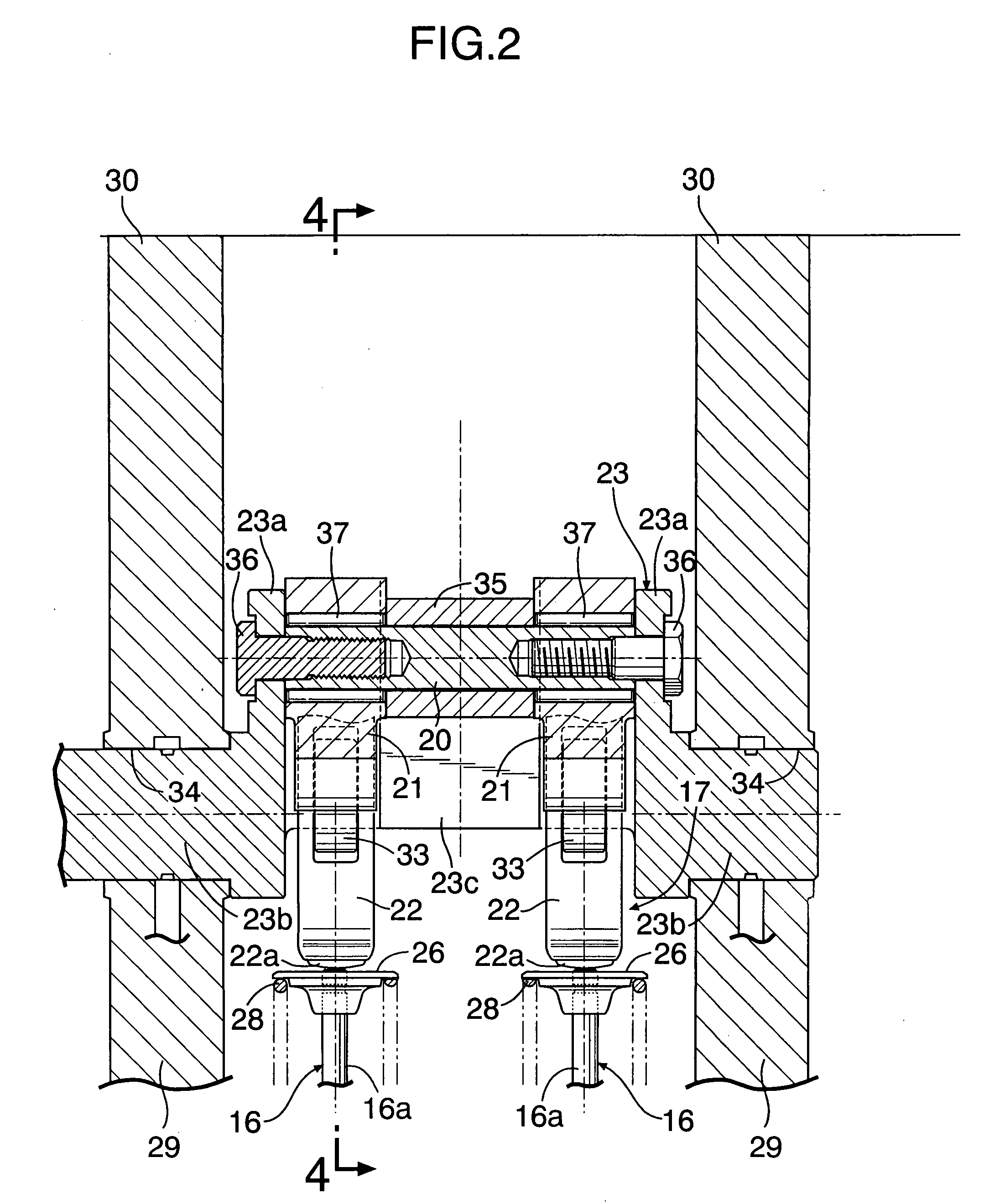
[0042] First, in FIGS. 1 to 4, intake valves 16 and 16 that are a pair of engine valves for each cylinder are openably and closably provided in a cylinder head 15 that constitutes part of an engine body 14. A variable lift valve operating mechanism 17 that openably and closably drives the intake valves 16 and 16 includes a cam shaft 19 having lift valve cams 18 and 18 corresponding to the intake valves 16 and 16, a pair of sub cams 21 and 21 that are supported pivotably by a movable support shaft 20 displaceable in a plane perpendicular to a rotation axis of the lift valve cams 18 and 18, that is, to an axis of the cam shaft 19, and pivoted following the lift valve cams 18 and 18, a pair of rocker arms 22 and 22 that are interlocked with and connected to the intake valves 16 and 16, and follow the sub cams 21 and 21, a control arm 23 that is connected to the movable support shaft 20, can be rotated around an axis parallel to the axis of the lift valve cams 18 and 18, that is, to the...


PUM


Abstract

In a default device of an actuator for a variable lift valve operating mechanism, in the event of failure of the actuator, a pressed portion of a lever pivotably supported on a support shaft is urged by a resilient force of a coil spring, an arm is pressed by a cam portion of the lever to rotate a control shaft in one direction to prevent valve lift from being a predetermined value or lower. The support shaft that pivotably supports the lever of a default mechanism is placed in a position offset from a rotation axis of the control shaft. Thus, as compared with the case where the support shaft is placed coaxially with the control shaft, a large urging force is input from the lever to the control shaft to reliably prevent the valve lift from being the predetermined value or lower.

Description

RELATED APPLICATION DATA [0001] The present invention is based upon Japanese priority application No. 2006-45199, which is hereby incorporated in its entirety herein by reference. BACKGROUND OF THE INVENTION [0002] 1. Field of the Invention [0003] The present invention relates to a default device of an actuator for a variable lift valve operating mechanism in which in the event of failure of the actuator that rotatably drives a control shaft of a variable lift valve operating mechanism capable of varying valve lift of an engine valve of an internal combustion engine, the control shaft is urged in one direction by an urging member of a default mechanism to prevent the valve lift from being a predetermined value or lower. [0004] 2. Description of the Related Art [0005] Japanese Patent Application Laid-Open No. 2000-227010 discloses a variable lift valve operating device of an internal combustion engine in which a control shaft is rotated by an electric motor via a drive gear and a dri...

Claims


Application Information

Patent Timeline
IPC IPC(8): F01L1/34
CPCF01L13/0021F01L2105/00F01L13/0063F01L2305/00
Inventor TSUTSUMI, MICHIHISAMARUYAMA, SHIGERU
Owner HONDA MOTOR CO LTD
Why Eureka
Try Eureka