Device for combined rotation of a shaft about its own axis

a technology of combined rotation and shaft, which is applied in the direction of piezoelectric/electrostrictive/magnetostrictive devices, electrical devices, couplings, etc., can solve the problems of rapid deterioration of spring efficiency and turfing apparatus malfunction

Inactive Publication Date: 2007-08-30
HOLMAC DI GASTALDI CHRISTIAN E C
View PDF28 Cites 2 Cited by
  • Summary
  • Abstract
  • Description
  • Claims
  • Application Information

AI Technical Summary

Benefits of technology

[0013] The aim of the present invention is to provide a device for the combined rotation of a shaft about its own axis which is capable of obviating the drawbacks shown by known types of device.
[0014] Within this aim, an object of the present invention is to provide a device which is more durable and efficient.
[0015] Another object of the present invention is to provide a device according to the invention which can be installed easily even in turfing machines of known types which are already in operation.
[0017] Another object of the present invention is to provide a device for the combined rotation of a shaft about its own axis which can be manufactured cheaply with known systems and technologies.
[0018] This aim and these and other objects, which will become better apparent hereinafter, are achieved by a device for the combined rotation of a shaft about its own axis, of the type which comprises a first body which is elongated diametrically with respect to an axis of rotation of a shaft to be turned, said first body being rigidly coupled to means for actuating a simple rotation of said first body about said axis, and a second diametrically elongated body, which is arranged transversely to said first body and is coaxial thereto, said second body being associated with said first body and being rigidly coupled to means for generating torsional vibrations about the axis of said simple rotation, said second body being adapted to perform angular movements with oscillations of reduced extent with respect to said first body and to support said shaft to be turned, elastic compression means being interposed between the adjacent consecutive portions of said first and second diametrically elongated bodies and being adapted to cushion small oscillations and facilitate their return, said device being characterized in that said elastic compression means are constituted, between each portion of the first body and said corresponding portions of the second body between which they are arranged, by at least one pair of elastic elements.

Problems solved by technology

For the actuation of arc-like blades having a larger diameter, up to 80 centimeters or more, it is necessary to have more power, and this leads, for known devices, to a stress which causes rapid deterioration of the efficiency of the springs, with consequent malfunction of the turfing apparatus.

Method used


Image

  • Device for combined rotation of a shaft about its own axis
  • Device for combined rotation of a shaft about its own axis
  • Device for combined rotation of a shaft about its own axis

Examples


first embodiment

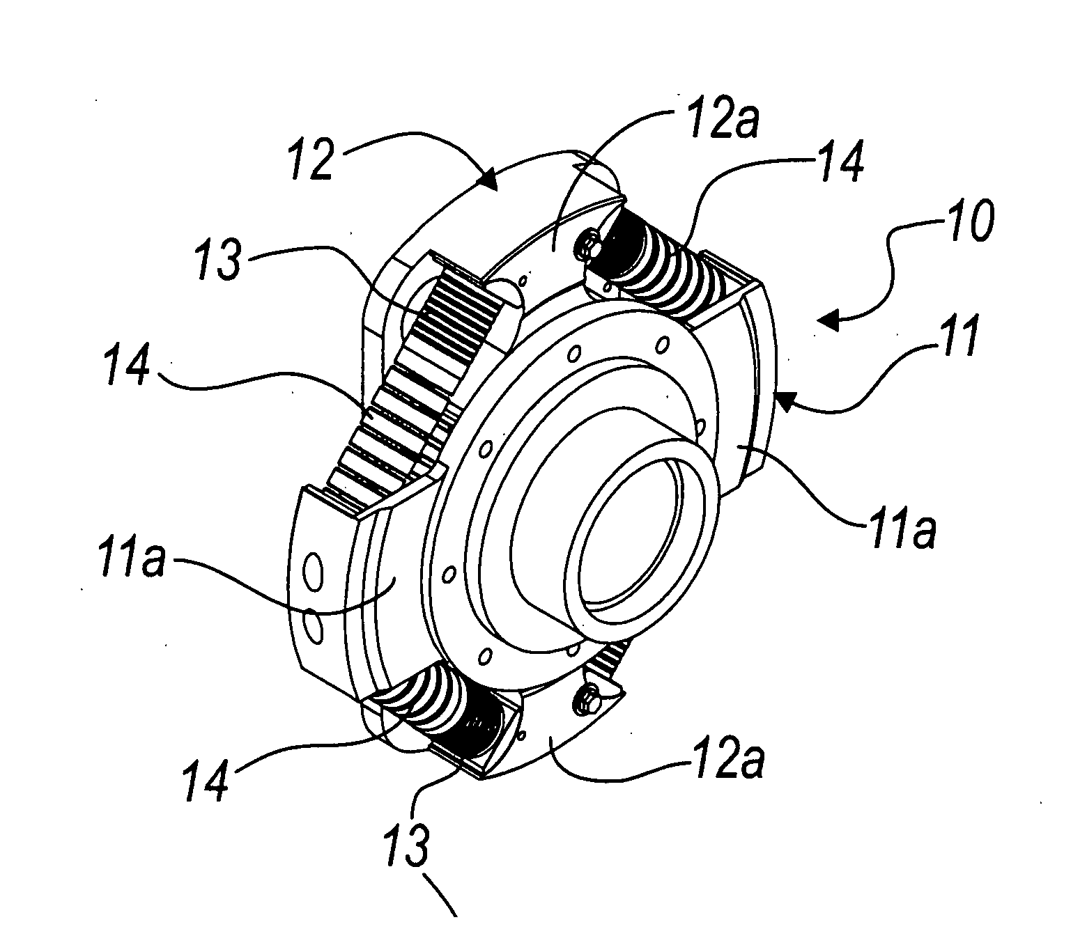
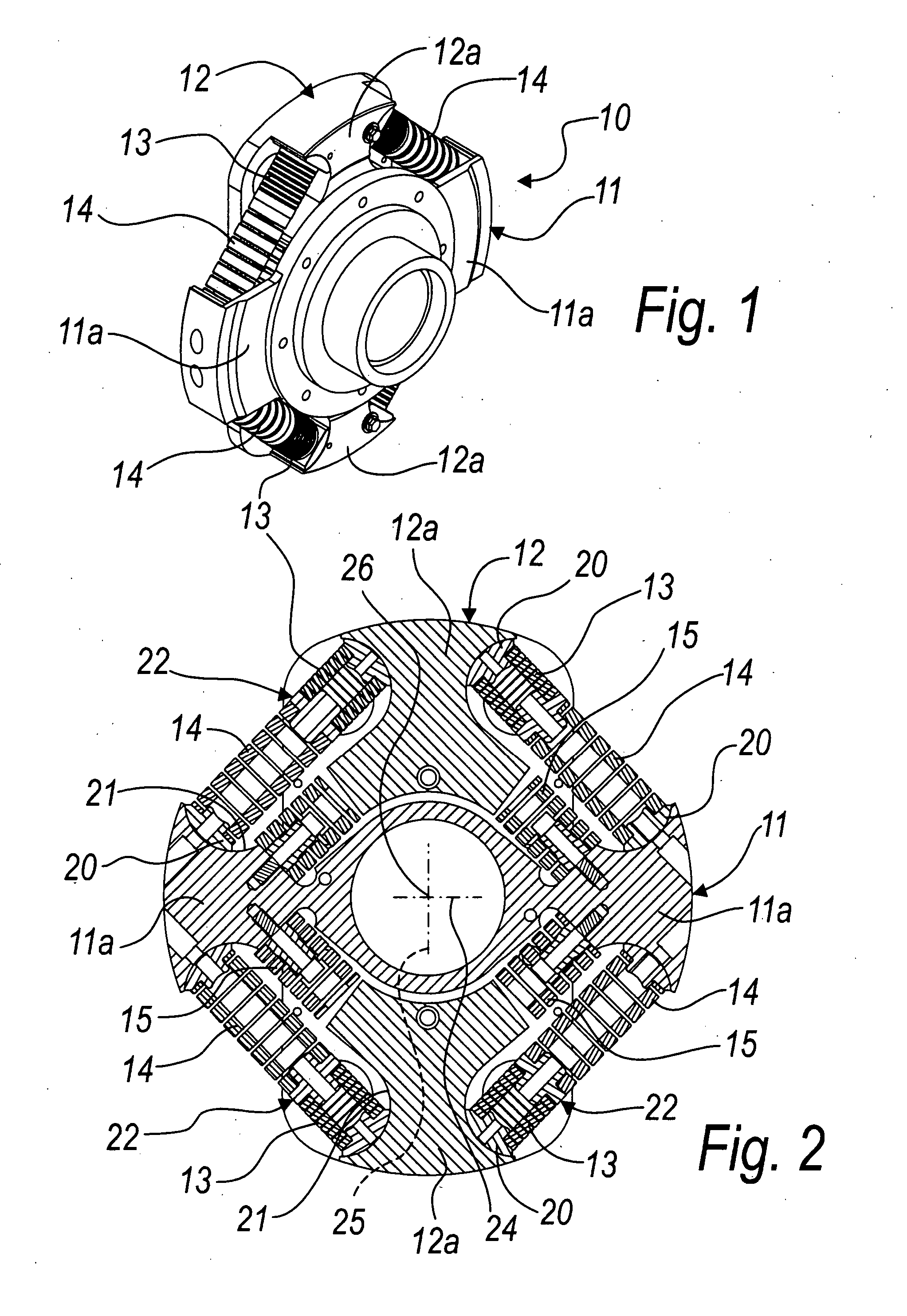
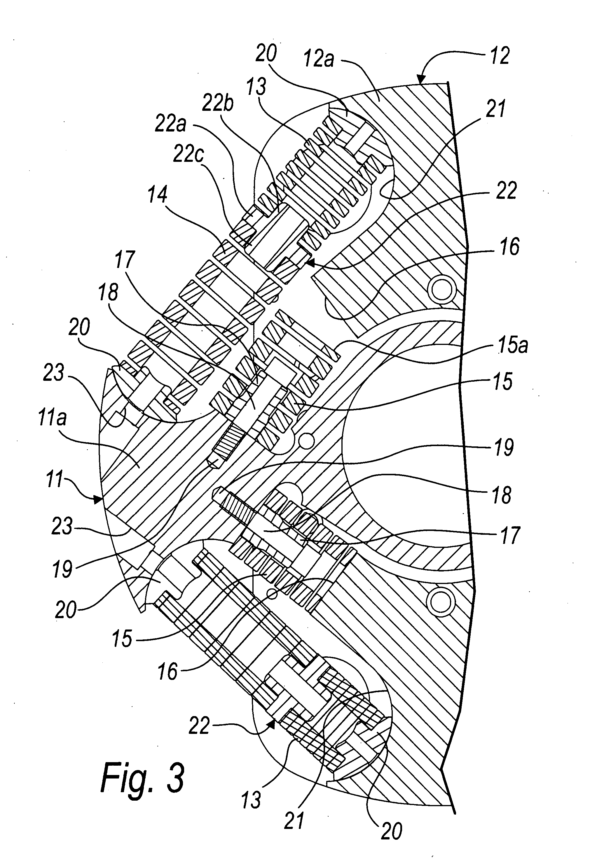
[0025] With reference to the figures, a device for the combined rotation of a shaft about its own axis according to the invention is designated generally by the reference numeral 10 in its first embodiment, which is shown in FIGS. 1 to 3.

[0026] The device 10 comprises a first body 11, which protrudes diametrically (extends on a diametrical direction) with respect to a rotation axis 26 of a shaft to be turned, which is not shown for the sake of simplicity.

[0027] The first body 11 is rigidly coupled to actuation means for actuating a simple rotation, which by means of the first body 11 reaches the shaft to be turned.

[0028] A second diametrically elongated body 12 (that extends on a further diametrical direction with respect to the rotation axis 26) is associated with the first body 11, lies transversely to the first body 11 and is coaxial thereto.

[0029] The second body 12 supports the shaft to be turned and is coupled to vibration means for generating torsional vibrations about the...

second embodiment

[0054] In the device according to the invention, designated by the reference numeral 110 in FIG. 4, two elastic elements in series are provided between two contiguous portions 111a and 112a of the two diametrically elongated bodies 111 and 112 and are arranged substantially in a tangential direction with respect to the substantially circular structure of the device 110.

[0055] Said two elastic elements in series are two cylindrical helical compression springs, as described for the first embodiment of the device 10.

[0056] There is therefore a first spring 113, which is adapted to work when actuated by relatively low torques, and a second spring 114, which is more rigid than the first spring 113 and is adapted to work when actuated by torques that are more intense or greater than those actuating the first spring.

[0057] The first spring 113 and the second spring 114 are coupled to the respective second body 112 and first body 111 on which they are suitable to push, each by way of the ...

third embodiment

[0061] In the device according to the invention, shown in FIG. 5 and designated therein by the reference numeral 210, there are, between two mutually proximate portions 211a and 212a of the diametrically elongated bodies 211 and 212, two elastic elements which are arranged in parallel, in a substantially tangential direction with respect to the substantially circular structure of the device 210.

[0062] Said elastic elements are constituted, between each portion 211a of the first body 211 and an adjacent portion 212a of the second body 212, by two springs 214 and 215 arranged in parallel.

[0063] A first outer spring 214 is coupled to the first body 211 and second body 212, against which it is suitable to push, by interposition with each of its ends of a dome-shaped element 220, which can slide in a corresponding complementarily shaped seat 221 formed in each of the bodies 211 and 212.

[0064] The second inner spring 215 has a normally free end 215a and is fixed with its opposite end 21...


PUM


Abstract

A device for the combined rotation of a shaft about its own axis, having a first body elongated diametrically with respect to the axis of the shaft, the first body being rigidly coupled to an actuation for simple rotation about the axis, and a second diametrically elongated body arranged transversely to the first body coaxial thereto. The second body is associated with the first body and is rigidly coupled to elements for generating torsional vibrations about the axis and performs alternating angular movements with reduced extent oscillations. The second body is adapted to support the shaft to be turned. A pair of elastic compression elements are interposed between the adjacent consecutive portions of the first and second bodies to cushion small oscillations.

Description

[0001] The present invention relates to a device for combined rotation of a shaft about its own axis. [0002] The expression “combined rotation” is used to reference a simple rotary motion in one direction, combined with an alternating coaxial angular motion of limited extent. BACKGROUND OF THE INVENTION [0003] Especially in the field of trussing equipment, devices are currently known and used extensively for subjecting the motor shaft, to which for example an arc-like excavation blade can be coupled during said turfing operations, to a combined rotation about its own axis. [0004] These known combined rotation devices generally comprise a first body which is elongated diametrically with respect to the axis of rotation of the driven shaft. [0005] Said first body is rigidly coupled to means for actuating a simple rotation of said first body about the axis of the shaft. [0006] Known devices further have a second body, which also is elongated diametrically, lies transversely to the first...

Claims


Application Information

Patent Timeline
Patent Type & Authority Applications(United States)
IPC IPC(8): H01L41/00
CPCF16D3/66F16F15/12366F16F3/04
Inventor LAZZARIN, FRANCO
Owner HOLMAC DI GASTALDI CHRISTIAN E C
Why Eureka
Try Eureka