System for masking print defects

a print defect and masking technology, applied in the field of printing systems, can solve the problems of high computational cost of such correction methods, image non-uniformity in the output image of digital imaging devices, visible objectionable print defects,

Active Publication Date: 2007-08-30
XEROX CORP
View PDF70 Cites 37 Cited by
  • Summary
  • Abstract
  • Description
  • Claims
  • Application Information

AI Technical Summary

Problems solved by technology

Image non-uniformity occurs in the output images of digital imaging devices, such as copiers, scanners, and printers, for a variety of reasons.
Even relatively small non-uniformities can give rise to visibly objectionable print defects.
Photoreceptor scratches, contamination of the charger wire, non-uniform LED imager output and Raster Output Scanner (ROS) spot size variations, and spatially varying pressure on a bias transfer roll are examples of subsystem defects which can give rise to rendered image streaking in a xerographic marking engine.
They are typically caused by time-varying performance of a marking engine subsystem, such as non-uniform velocity of the photoreceptor drive, out-of-roundness of development rolls, and wobble of the ROS polygon mirror.
Other defects which may arise include and mottle and graininess.
However, the computational cost of such correction methods is high, particularly in the case of color images.

Method used


Image

  • System for masking print defects
  • System for masking print defects
  • System for masking print defects

Examples


Embodiment Construction

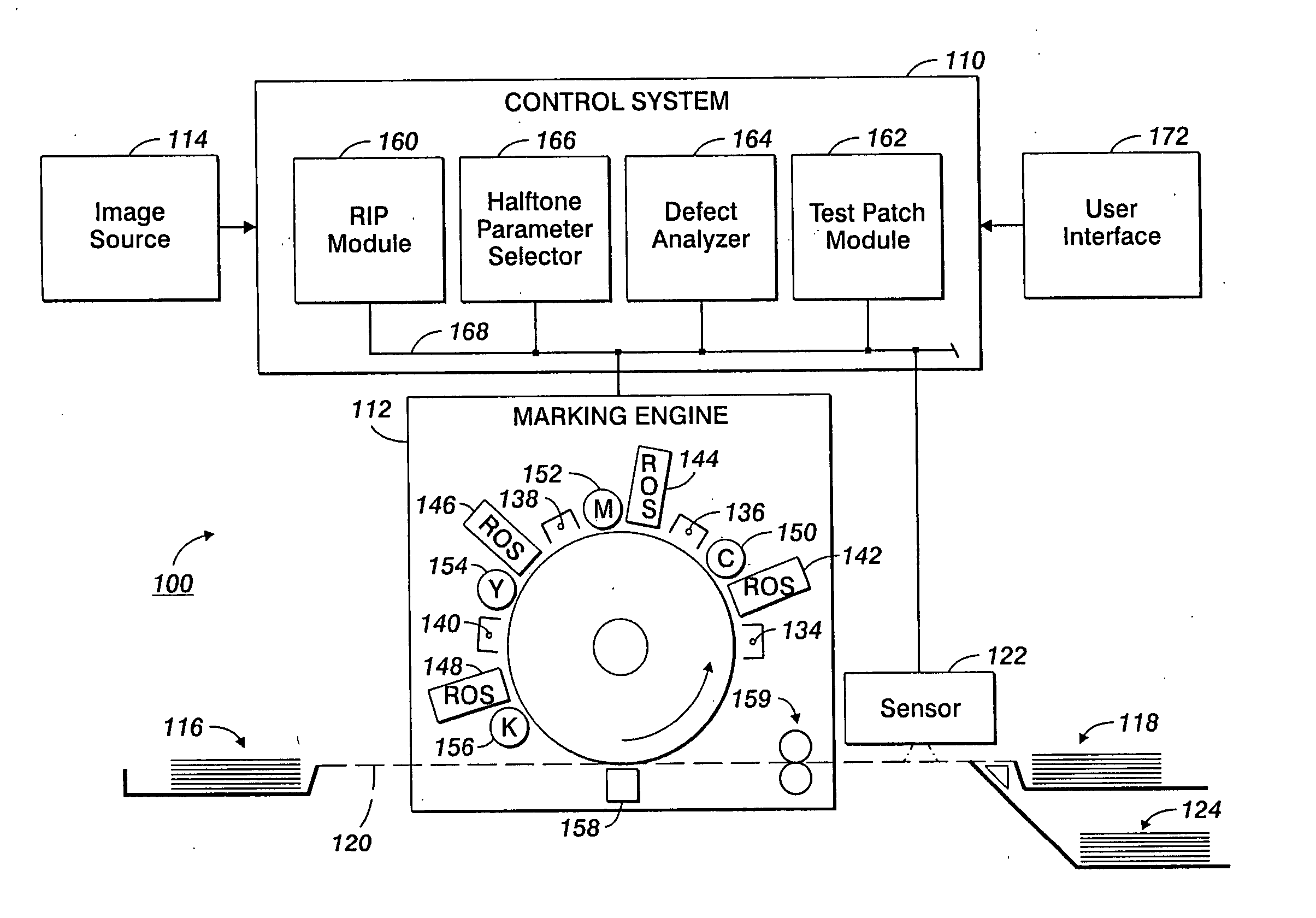
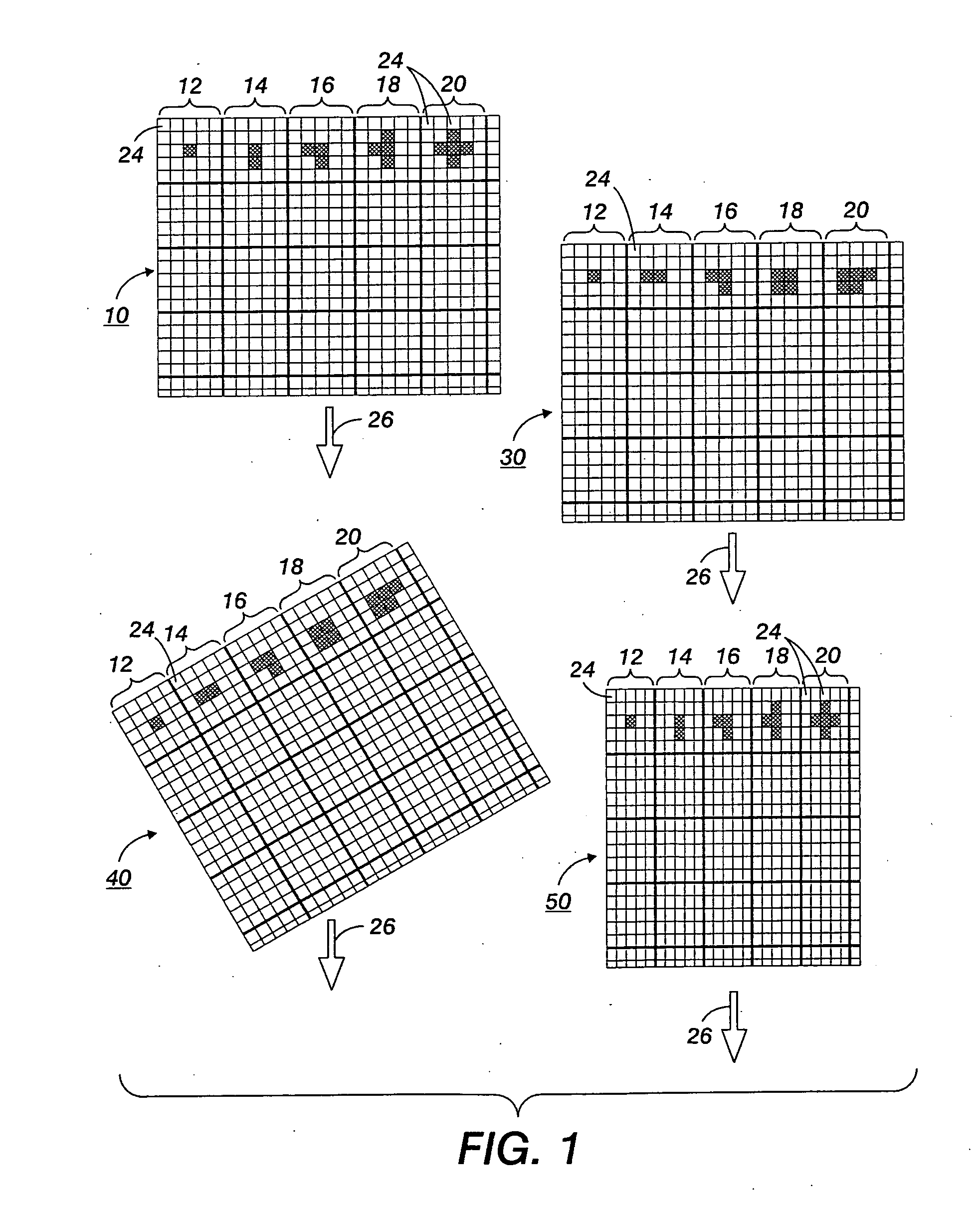
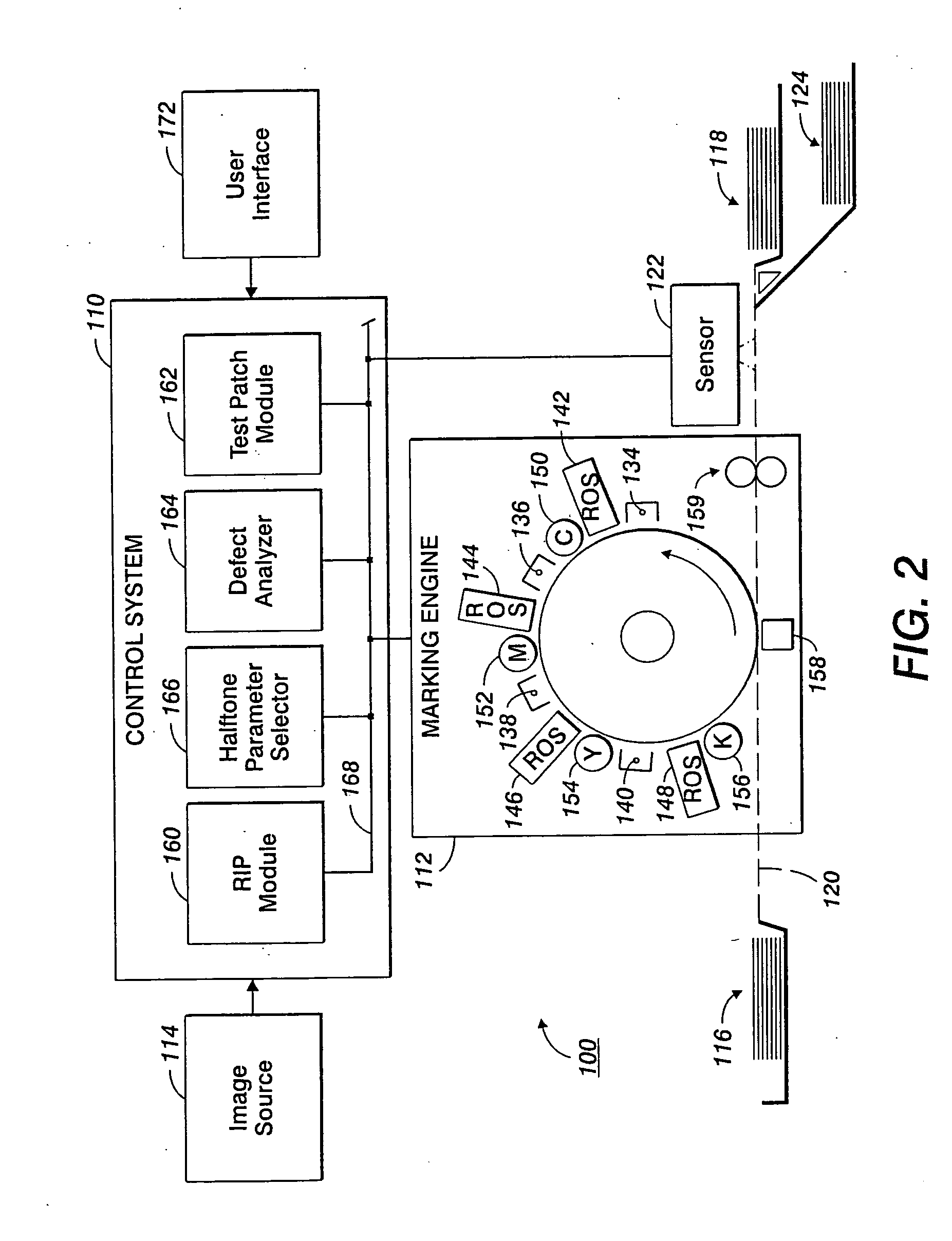
[0021] The exemplary embodiment relates to a system and a method for reducing print non-uniformity in printed images which give rise to visibly objectionable print defects in the image.

[0022] In one aspect, a method of printing includes determining a defect state of a printing system, selecting a screen with a halftone print parameter which masks the defect, and printing images according to the selected halftone print parameter.

[0023] In another aspect, a method includes determining a defect state of a printing system and selecting a marking engine from a plurality of marking engines which masks the defect, and printing images on that marking engine.

[0024] In another aspect, a printing system includes at least one marking engine, which renders images on print media, and a sensor which senses print defects on printed media. A control system is configured for receiving print defect data from the sensor and selecting a screen with one or more halftone print parameter for masking the...


PUM


Abstract

A method of printing includes, on an ongoing basis, determining a print defect state of a printing system, selecting a screen which has a halftone print parameter which masks a detected print defect, such as one or more of a screen frequency parameter, a screen angle parameter, and a dot growth parameter. The method further includes printing images according to the selected halftone print parameter. Alternatively, where the printing system includes more than one marking engine, the method includes selecting a marking engine according to the determined defect states of each of the marking engines.

Description

CROSS REFERENCE TO RELATED PATENTS AND APPLICATIONS [0001] The following applications, the disclosures of which are totally incorporated herein by reference, are mentioned: [0002] U.S. patent application Ser. No. 10 / 922,316, entitled METHOD AND SYSTEMS ACHIEVING PRINT UNIFORMITY USING REDUCED MEMORY OR COMPUTATIONAL REQUIREMENTS, filed Aug. 19, 2004, by Zhang, et al.; [0003] U.S. application Ser. No. 11 / 143,818 (Attorney Docket No. 20040621-US-NP) entitled INTER-SEPARATION DECORRELATOR, filed Jun. 2, 2005, by Dalal, et al.; [0004] U.S. application Ser. No. 10 / 923,166, entitled UNIFORMITY COMPENSATION IN HALFTONED IMAGES, filed Aug. 20, 2004, by Zhang, et al.; [0005] U.S. application Ser. No. 10 / 999,326, filed Nov. 30, 2004, entitled SEMI-AUTOMATIC IMAGE QUALITY ADJUSTMENT FOR MULTIPLE MARKING ENGINE SYSTEMS, by Robert E. Grace, et al.; [0006] U.S. application Ser. No. 11 / 070,681, filed Mar. 2, 2005, entitled GRAY BALANCE FOR A PRINTING SYSTEM OF MULTIPLE MARKING ENGINES, by R. Enriq...

Claims


Application Information

Patent Timeline
Patent Type & Authority Applications(United States)
IPC IPC(8): G06F15/00G06K15/00
CPCG03G15/5062G03G15/55H04N1/4055H04N1/4015G03G2215/00021
Inventor ANDERSON, DAVID G.PAUL, PETER
Owner XEROX CORP
Why Eureka
Try Eureka