
Magnetic head slider

a slider and magnetic head technology, applied in the direction of maintaining the head carrier alignment, recording information storage, instruments, etc., can solve the problems of increasing heat loss, difficult to achieve expected minimization, and conventional heating portion failure to dissipate a predetermined amount of hea

Inactive Publication Date: 2007-08-30
WESTERN DIGITAL TECH INC
View PDF13 Cites 13 Cited by
  • Summary
  • Abstract
  • Description
  • Claims
  • Application Information

AI Technical Summary

Benefits of technology

[0006]In a conventional magnetic head slider having an incorporated heater for controlling a magnitude of floating, since terminal portions of the heater are produced at a step different from a step of producing lead portions thereof, a resistance offered by the lead portions increases due to a contact resistance occurring at the overlaps between the terminal portions and lead portions. This increases a heat loss. Consequently, a conventional heating portion fails to dissipate a predetermined amount of heat. This makes it difficult to achieve expected minimization of a magnitude of floating and can lead to a failure in filling the role of a thin-film magnetic head.

Problems solved by technology

This increases a heat loss.
Consequently, a conventional heating portion fails to dissipate a predetermined amount of heat.
This makes it difficult to achieve expected minimization of a magnitude of floating and can lead to a failure in filling the role of a thin-film magnetic head.

Method used


Image

  • Magnetic head slider
  • Magnetic head slider
  • Magnetic head slider

Examples


Embodiment Construction

[0022]Embodiments in accordance with the present invention relate to a slider structure for realizing a high recording density in a magnetic disk unit. More particularly, embodiments of the present invention are concerned with a magnitude-of-floating adjusting slider having the ability to adjust the distance between a magnetic disk and a magnetic head.

[0023]An object of an embodiment of the present invention is to diminish a change in a resistance offered by lead portions of a heater intended to adjust a magnitude of floating of a slider.

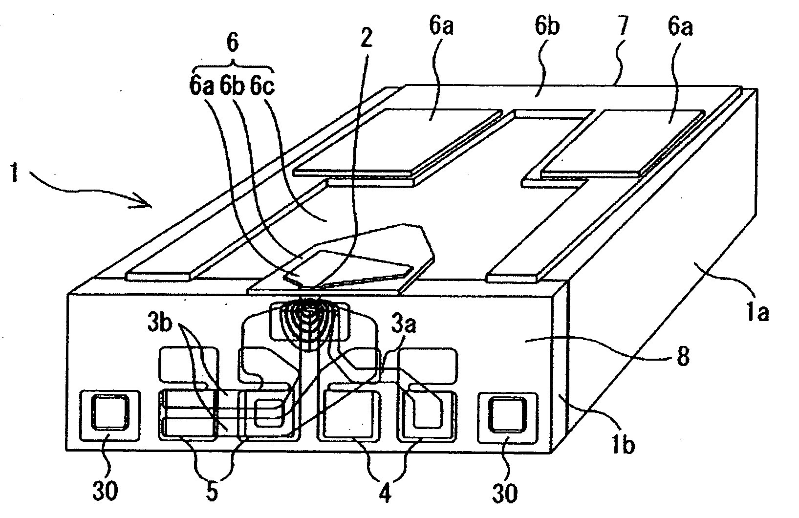
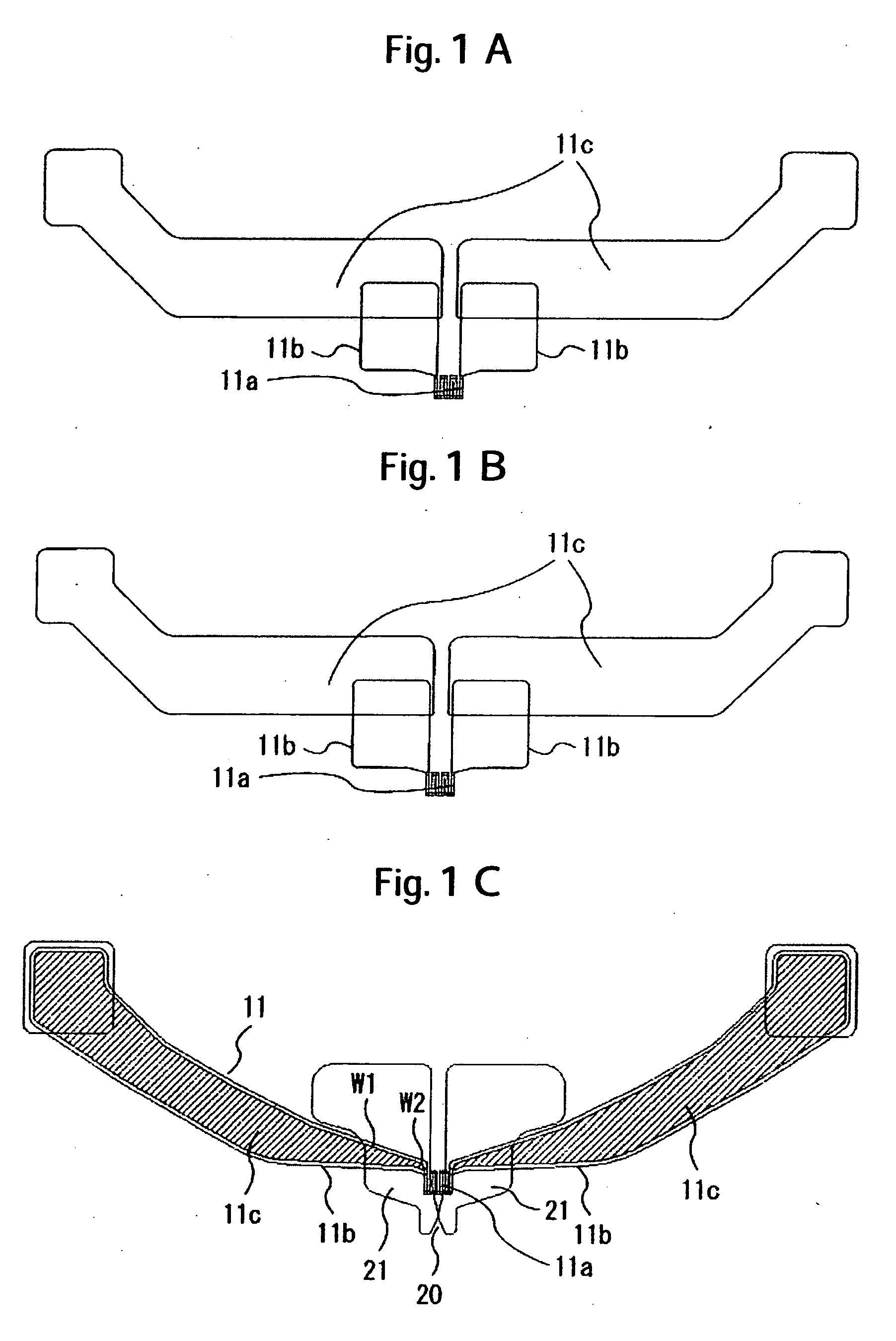
[0024]In order to accomplish the above object, a magnetic head slider in accordance with an embodiment of the present invention includes a magnetic head and a heater which are formed in an air outflow end surface of the slider. The heater includes a heating portion, terminal portions that extend from both ends of the heating portion, and lead portions that overlap the respective terminal portions at an overlap ratio of approximately 50% or more.

[002...


PUM

PropertyMeasurementUnit
resistanceaaaaaaaaaa

Abstract

Embodiments in accordance with the present invention provide a magnetic head slider which includes a magnetic recording / reproducing element and a heater which are formed in an air outflow end surface of a slider. The heater includes a heating portion, terminal portions extending from both ends of the heating portion, and lead portions overlapping the respective terminal portions at an overlap ratio of approximately 50% or more.

Description

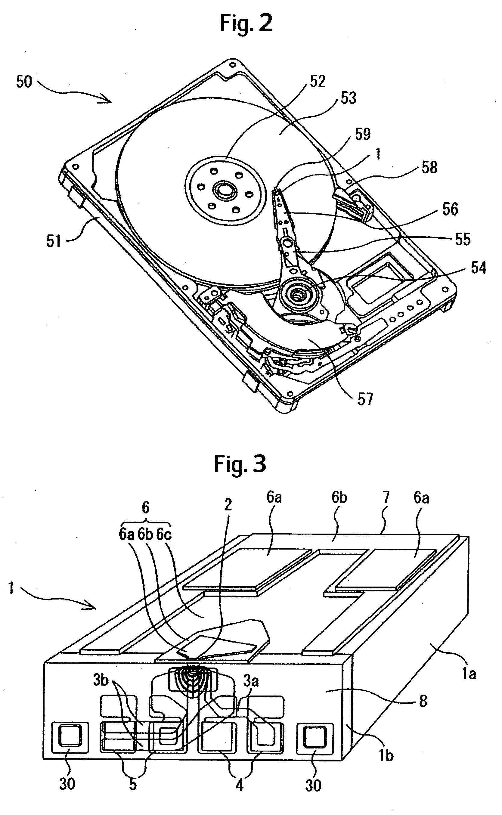
CROSS-REFERENCE TO RELATED APPLICATION[0001]The instant nonprovisional patent application claims priority to Japanese Patent Application 2006-051792, filed Feb. 28, 2006 and incorporated by reference in its entirety herein for all purposes.BACKGROUND OF THE INVENTION[0002]A magnetic disk unit includes a magnetic disk that rotates and a slider in which a magnetic recording / reproducing element included in a magnetic head is incorporated and which is borne by a suspension. The slider relatively travels over a magnetic disk, and the magnetic recording / reproducing element writes or reads magnetic information in or from the magnetic disk. The slider floats as an air lubrication bearing due to the wedge film effect of air, whereby the magnetic disk and slider do not come into solid contact with each other. In order to realize a magnetic disk unit featuring a high recording density and a large capacity stemming from the high recording density or a compact design, it would prove effective to...

Claims


Application Information

Patent Timeline
Patent Type & Authority Applications(United States)
IPC IPC(8): G11B5/60
CPCG11B5/6064G11B5/6005
Inventor KATO, ATSUSHISHIRAKI, KIYONORIYAMAGUCHI, KOUJI
Owner WESTERN DIGITAL TECH INC
Learn More