Central monitoring station with method to process call based on call source identification information

a central monitoring station and call source technology, applied in the field of security systems, can solve problems such as the disconnecting of calls of monitoring stations, and achieve the effect of increasing the efficiency of the alarm answering process

Active Publication Date: 2007-08-30
ADEMCO INC
View PDF8 Cites 9 Cited by
  • Summary
  • Abstract
  • Description
  • Claims
  • Application Information

AI Technical Summary

Benefits of technology

[0006] The present invention is a system and a method for processing an incoming telephone call to an alarm system central monitoring station using call source identification information (such as caller ID, DNIS, or ANI). The central monitoring station uses the call source identification information transmitted by the telephone system (typically between the first and second ring of a call) to make decisions as to how to process the call prior to the receiver answering the call. The central monitoring station will process the call by checking if the call source identification information matches call source identification information stored in memory, and it will check status data that may be associated with the call source identification information, also stored in memory, to determine if the call should be disconnected, transferred, or connected to the receiver. Since the receiver only processes valid (legitimate) local alarm system reports, the lines are less likely to be tied up by invalid alarm calls and the efficiency of the alarm answering process is increased.

Problems solved by technology

Connecting the call to a second receiver or a second line of a receiver would likely take place when there is an interface problem between the alarm system panel and the central monitoring station, and disconnecting the call would likely take place when there is a significant problem such as a runaway dialer.
In this embodiment all call source identification information stored in memory has a problem status that causes the central monitoring station to disconnect the call.

Method used


Image

  • Central monitoring station with method to process call based on call source identification information
  • Central monitoring station with method to process call based on call source identification information
  • Central monitoring station with method to process call based on call source identification information

Examples


first embodiment

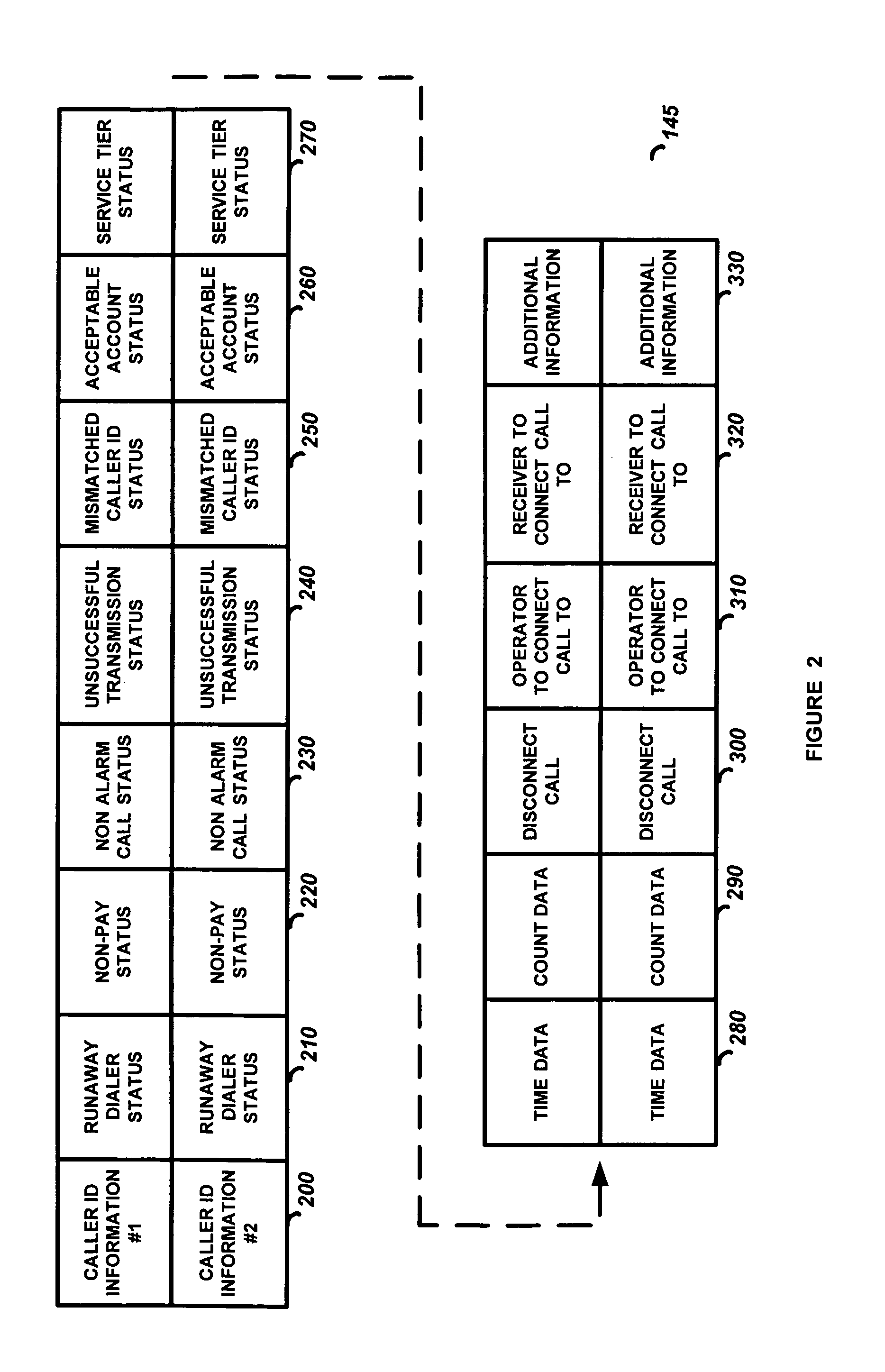
[0022]FIG. 2 is a diagram of a section of memory that shows how the status information 145 may be stored. Shown is a list of caller ID information 200 and the status bits (or bytes) 210-330 associated with each caller ID information 200. In the present invention only the caller ID information 200 is stored in memory 140. The status bits 210-330 are not necessary because, in this simplified embodiment, all the alarm systems whose caller ID information 200 has been stored in memory 140 have been previously determined to be invalid (likely a runaway dialer or a non-alarm call) which will cause its telephone calls to be disconnected by the receiving circuits 110 until the memory 140 is reprogrammed. That is, the mere fact that the caller ID is stored in memory (with no other status detail as in the next described embodiments) indicates there is a problem with the calling alarm system. For example, in order to disconnect an invalid alarm call, the call would likely be answered and then i...

second embodiment

[0023] In the present invention the caller ID information 200 and some of the status bits 210-330 will be stored in memory 140 when it has been determined that a particular alarm system has a problem. In this embodiment the call may be disconnected by the receiving circuits 110 or may be transferred by the switching circuits 120 depending on the stored status information 145. The memory 140 may be programmed with the caller ID information 200, the runaway dialer status bit 210 set and disconnect call bit 300 set. In this case a call by the alarm system with this caller ID information 200 will be disconnected by the receiving circuits 110. The memory 140 may be programmed with the caller ID information 200, the non-paying subscriber status bit 220 set and the receiver to connect the call to byte 320 programmed. In this case the alarm call will be transmitted to the receiver 150 whose address is programmed in the receiver byte 320, and the monitoring operator 180 will answer the alarm...

third embodiment

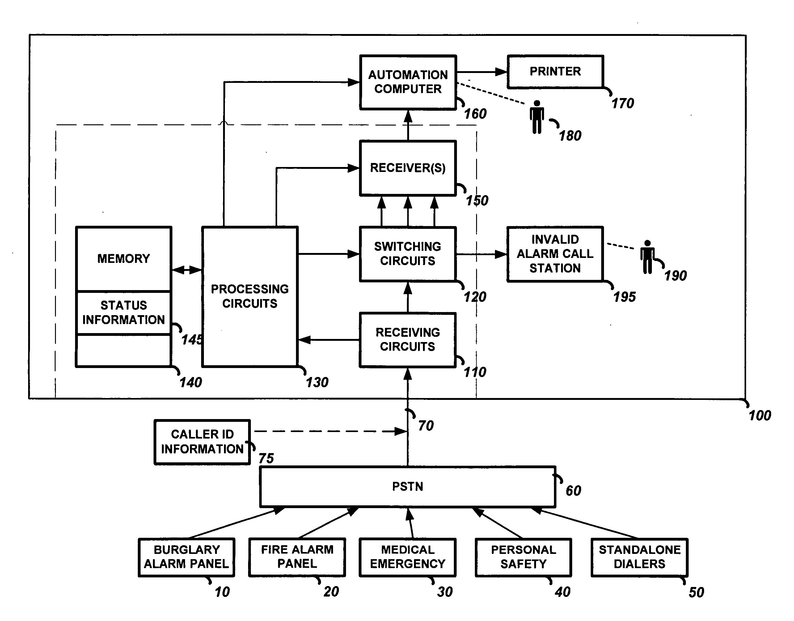
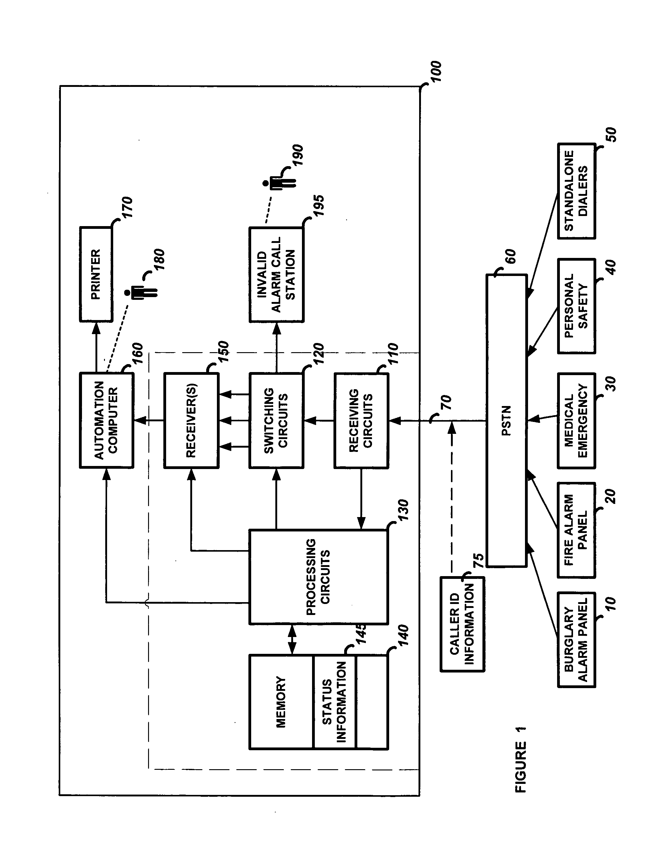
[0027]FIG. 5 is a flowchart of the present invention. In this embodiment the central monitoring station 100 receives a telephone call which is detected by receiving circuits 110. The receiving circuits 110 read the caller ID information 75 and the processing circuits 130 look for a match between the received caller ID information 75 and the caller ID information 200 stored in memory 140. If a match is not found, the processing circuits 130 cause the switching circuits 120 to connect the call to the invalid alarm call station 195. The business operator 190 will determine if the status information 145 should be programmed into memory 140. If there is a match, the processing circuits 120 read the status bits 210-330 associated with the caller ID information 200. If the processing circuits 120 determine the call is a valid alarm call, the processing circuits 130 cause the switching circuits 120 to connect the call to the receiver 150 and transmit the status information 145. The status i...


PUM


Abstract

A system and a method for processing an incoming telephone call to an alarm system central monitoring station using call source identification data such as caller ID. The alarm system central monitoring station can use the caller ID information transmitted by the telephone company to make decisions as to how to process a call prior to the central monitoring station receiver answering the call. The central monitoring station will process the call by checking if the caller ID information matches caller ID information stored in memory and it will check status information associated with the caller ID information to determine if the call should be disconnected, transferred, or connected. In order to accomplish this the central monitoring station comprises receiving circuits for detecting an incoming telephone call on the telephone line and reading caller ID information associated with the call, switching circuits coupled to the receiving circuitry for transferring the call if necessary, memory for storing status information comprising the caller ID information, and processing circuitry for determining if caller ID information has been stored in the memory, and if it has, then accessing the status information and processing the call as a function of the status information. The central monitoring station may process the call by 1) transferring the call to an invalid alarm call station, 2) connecting the call to a central monitoring station receiver, a second central monitoring station receiver, or a second line of a central monitoring station receiver, or 3) disconnecting the call.

Description

TECHNICAL FIELD [0001] This invention relates to security systems, and in particular to an alarm system central monitoring station that processes an incoming telephone call based on the call source identification information such as caller ID. BACKGROUND ART [0002] Many different alarm systems, such as burglary, fire, medical emergency, and personal safety, transmit information to central monitoring stations over public telephone lines. When an alarm system calls the central monitoring station, the central monitoring station receiver answers the call, reads the information transmitted over the telephone line from the alarm system panel, and sends the information to an automation computer through a switching network which is controlled by a configuration computer. The information from the alarm system panel is displayed via the automation computer to a monitoring operator (a live person) and may also be printed by a printer. The monitoring operator screens the information and determi...

Claims


Application Information

Patent Timeline
Patent Type & Authority Applications(United States)
IPC IPC(8): H04M11/04
CPCH04M3/42034H04M3/42059H04M3/42068H04M2242/04H04M11/04H04M2203/6045H04M3/436
Inventor MARTIN, CHRISTOPHER D.BOODOOSINGH, NARINEHINKSON, RICHARD H.
Owner ADEMCO INC
Why Eureka
Try Eureka