Vehicle control apparatus

a control apparatus and clutch technology, applied in the direction of clutches, non-mechanically actuated clutches, gearing elements, etc., can solve the problems of easy deterioration of the diaphragm spring provided on the clutch (as described above), and achieve the effect of avoiding the promotion of deterioration of the diaphragm spring

Inactive Publication Date: 2007-08-30
HITACHI LTD
View PDF8 Cites 24 Cited by
  • Summary
  • Abstract
  • Description
  • Claims
  • Application Information

AI Technical Summary

Benefits of technology

[0011]A vehicle control apparatus in accordance with this invention can shut off power supply after detecting the vehicle status and engaging the clutch. Therefore, after the key switch is turned off, the vehicle control apparatus does not leave the clutch engaged and can avoid promotion of deterioration of the diaphragm spring.

Problems solved by technology

However, the diaphragm spring provided on the clutch (as described above) may be easily deteriorated if the key switch is turned off and the clutch is disengaged for a long time.

Method used


Image

  • Vehicle control apparatus
  • Vehicle control apparatus
  • Vehicle control apparatus

Examples


embodiment 1

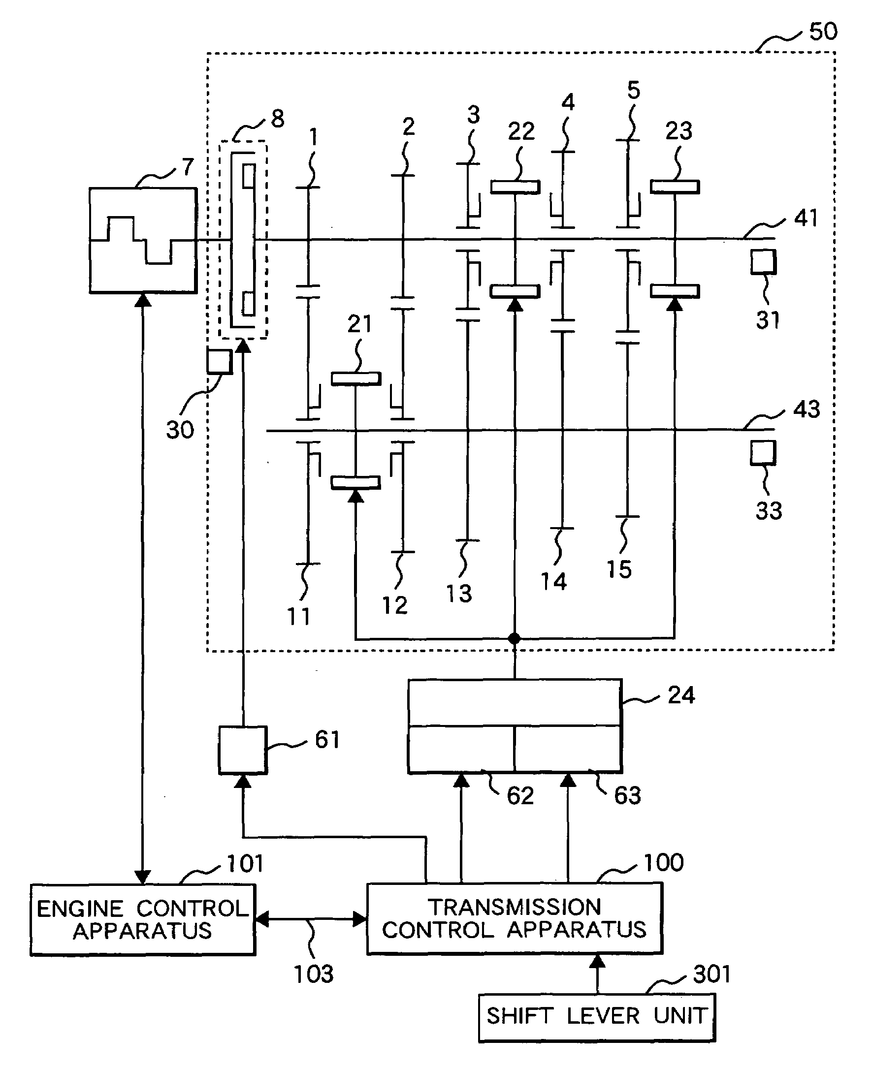
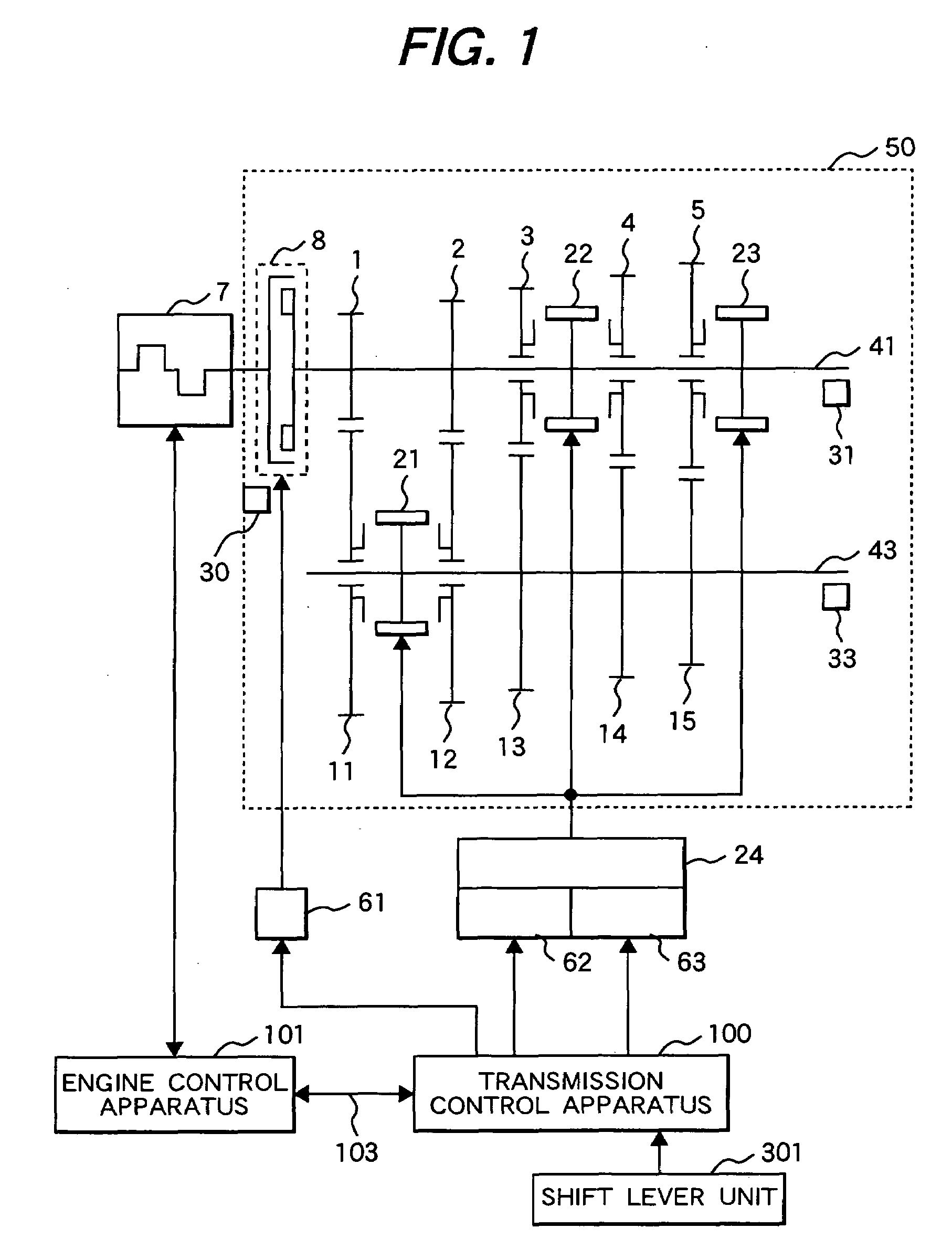
[0023]First will be explained an example of configuration of a vehicle control apparatus that is equipped with the friction transfer mechanism and an electrically-operated mechanism in accordance with this invention by referring to FIG. 1.

[0024]FIG. 1 shows a skeletal diagram of a vehicle system configuration equipped with a control apparatus which is an embodiment of this invention.

[0025]The vehicle system is equipped with engine 7 which is a driving power source, an engine speed sensor (not shown in the figure) which measures the number of revolutions of engine 7, an electronic controlled throttle valve (not shown in the figure) and a fuel injection unit (not shown in the figure) to inject an adequate quantity of fuel which matches with the air suction rate. Engine control apparatus 101 exactly controls torque of engine 7 by adjusting suction air rate, fuel injection rate, ignition timing, etc. There are two kinds of fuel injection units: intake port injection method which injects...

embodiment 2

[0104]Referring to FIG. 7 to FIG. 10, next will be explained another controlling example of a vehicle control apparatus which is different from the embodiment of FIG. 4 to FIG. 6

[0105]FIG. 7 shows a control flow for a system stop of the vehicle control apparatus which is another embodiment of this invention.

[0106]The content of FIG. 7 is programmed into the computer in transmission control apparatus 100 and repetitively executed at preset intervals. In other words, Step 701 to Step 710 below are executed by transmission control apparatus 100.

[0107]At Step 701, the control apparatus checks whether key switch signal KeySW is ON (to start) or OFF (to stop). When key switch signal KeySW is ON (to start), control is transferred to Step 710 (for ordinary operation). At Step 710, the control apparatus controls input shaft clutch actuator 61, shaft actuator 62, and select actuator 63 according to a requested operation (launching or gear-shifting) by using range position signal RngPos, accel...


PUM


Abstract

A vehicle equipped with a motor-operated mechanism that contains a clutch. The pushing member of the clutch is energized against a friction plane by an energizing mechanism and transfers power from a driving power source when it touches the friction plane. The location of the pushing member can be retained even when power is shut off. This structure prevents promotion of deterioration of a diaphragm spring in a state in which the clutch remains disengaged when the key switch is turned off.
After a signal from the key switch stops, the control apparatus stops the driving power source and the vehicle, engages the friction transfer mechanism, and then stops the system.

Description

CLAIM OF PRIORITY[0001]The present application claims priority from Japanese application serial no. 2006-49481, filed on Feb. 27, 2006, the content of which is hereby incorporated by reference into this application.FIELD OF THE INVENTION[0002]This invention relates to a vehicle control apparatus and more particularly to controlling of a friction transfer mechanism.BACKGROUND OF THE INVENTION[0003]Recently, an automatic clutch system has been developed which uses a gear type transmission for manual transmission and automates operation of a clutch which is a friction mechanism. Further, an automated manual transmission (hereinafter abbreviated as “automated MT”) has also been developed which automates operations of a clutch and a synchromesh mechanism.[0004]The automatic clutch and the automated MT respectively launch a vehicle by gradually engaging a clutch that connects and disconnects torque of an engine which is a driving power source. Further, when a transmission starts, the auto...

Claims


Application Information

Patent Timeline
Patent Type & Authority Applications(United States)
IPC IPC(8): B60W10/02F16D48/06F16H59/04F16H59/40F16H61/28F16H61/68F16H61/682
CPCB60W10/02B60W10/06B60W10/11B60W30/19F16D28/00Y10T477/75F16D2500/1025F16D2500/3069F16D2500/31493F16D2500/502F16D2500/70424F16D48/064
Inventor MATSUMURA, TETSUOYOSHIDA, YOSHIYUKIFUJIMOTO, KINYASHISHIDO, KENTARO
Owner HITACHI LTD
Why Eureka
Try Eureka