AI technical title is built by Patsnap AI team. It summarizes the technical point description of the patent document.
a technology of electrosurgical and electrode, applied in the field of electrosurgical system, can solve the problems of large and sudden changes in the voltage between the electrodes or the current flowing therebetween, and achieve the effects of reducing the voltage and reducing the power of the radio frequency signal
Active Publication Date: 2007-08-30
GYRUS MEDICAL LTD
View PDF6 Cites 8 Cited by
Summary
Abstract
Description
Claims
Application Information
AI Technical Summary
This helps you quickly interpret patents by identifying the three key elements:
Problems solved by technology
Method used
Benefits of technology
Benefits of technology
[0007] Preferably, the controller is adapted to change the radio frequency signal by reducing the power thereof when the predetermined criteria indicating the onset of a flare-out is met. Alternatively, the controller may reduce the voltage of the radio frequency signal, or even the frequency thereof. Where the radio frequency signal comprises a signal having dual components at a first and second frequency, the controller may change the signal by adjusting the relative proportions of the first and second frequency components. Preferably, however, the controller is adapted to reduce the power of the radio frequency signal, and may reduce it substantially to zero when the characteristic meets the predetermined criterion. Conveniently, the power is reduced substantially to zero for a period of at least 5 seconds, allowing time for the instrument to be withdrawn from the surgical site and the electrodes to be cleaned if necessary. Alternatively the power is reduced to zero until the operator of the instrument manually resets the instrument.
[0008] In one convenient arrangement, the controller is adapted to reduce the power of the radio frequency signal supplied between the first and second electrodes only when the aspect of the characteristic meets the predetermined criterion for a predetermined period of time. This serves to ensure that a false detection of a flare-out is not triggered by a transient change in the measured characteristic. The system may require a series of repeated measurements of the characteristic to all fit the predetermined criteria before action is taken.
Problems solved by technology
These include rapid changes in the impedance experienced between the electrodes, leading to large and sudden changes in the voltage between the electrodes or the current flowing therebetween.
Method used
Image
Click on the blue label to locate the original text in one second.
Reading with bidirectional positioning of images and text.
Examples
Embodiment Construction
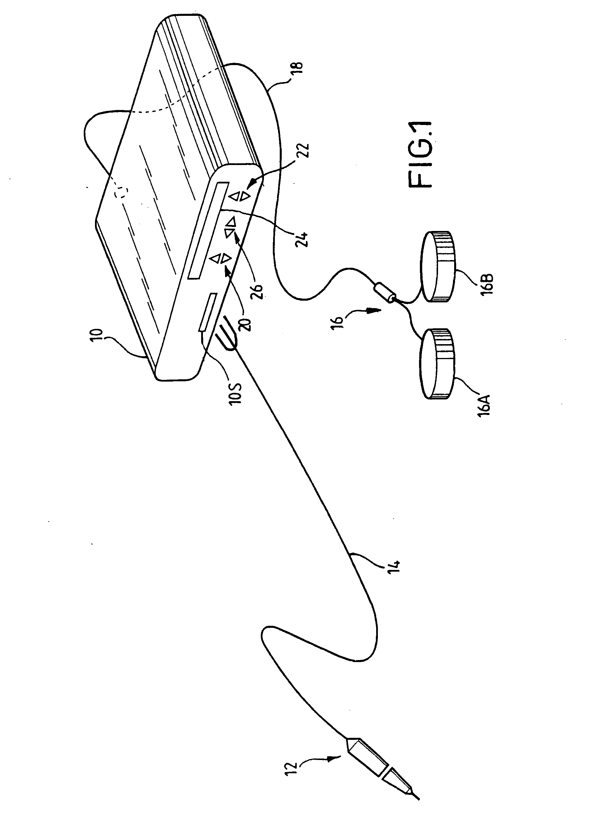
[0020] Referring to FIG. 1, a generator 10 has an output socket 10S providing a radio frequency (RF) output for an instrument 12 via a connection cord 14. Activation of the generator may be performed from the instrument 12 via a connection in cord 14 or by means of a footswitch unit 16, as shown, connected to the rear of the generator by a footswitch connection cord 18. In the illustrated embodiment footswitch unit 16 has two footswitches 16A and 16B for selecting a coagulation mode and a cutting mode of the generator respectively. The generator front panel has push buttons 20 and 22 for respectively setting coagulation and cutting power levels, which are indicated in a display 24. Push buttons 26 are provided as an alternative means for selection between coagulation and cutting modes.
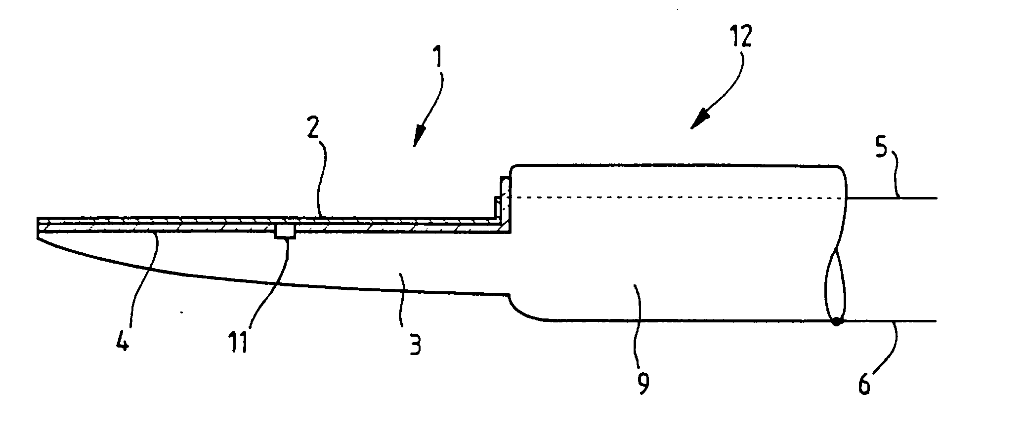
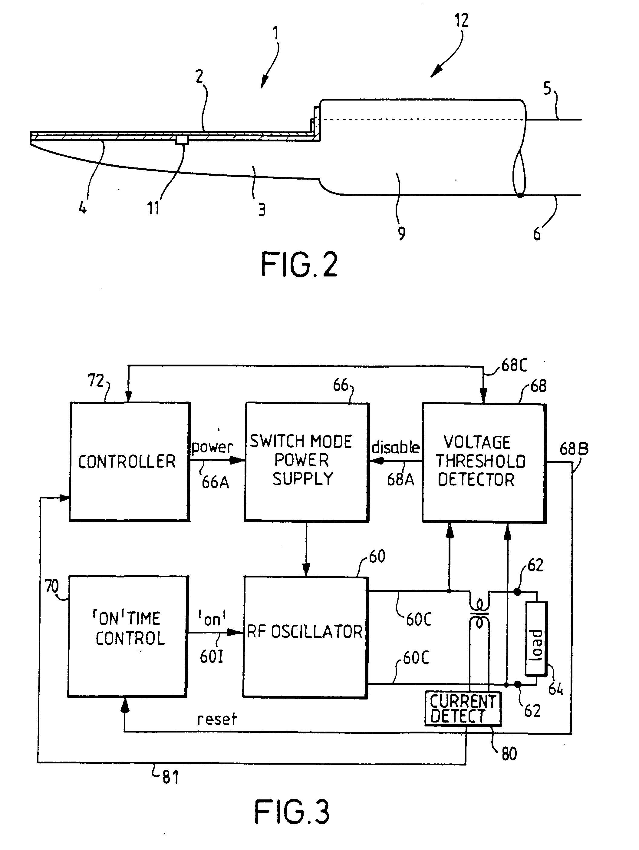
[0021] Referring to FIG. 2, the instrument 12 comprises a blade shown generally at 1 and including a generally flat first electrode 2, a larger second electrode 3 and an electrical insulator 4 separat...
PUM
Abstract
An electrosurgical system comprises a generator and an instrument including a first electrode, a second electrode, and an insulating spacer separating the first and second electrodes. The generator repeatedly measures a characteristic of the radio frequency output such as the impedance between the first and second electrodes. The generator analyses the impedance measurements, and interrupts the radio frequency signal when the rate of change of the impedance is such as to indicate the onset of a “flare-out”. In this way, the power is reduced before the flare-out leads to permanent damage or failure of the instrument.
Description
[0001] This is a Continuation of application Ser. No. 10 / 464,778, filed Jun. 19, 2003, which claims the benefit of U.S. Provisional Application No. 60 / 402,555, filed Aug. 12, 2002. The disclosure of the prior applications is hereby incorporated by reference herein in its entirety.FIELD OF THE INVENTION [0002] This invention relates to an electrosurgical system, and in particular to one in which an electrosurgical generator provides a radio frequency cutting signal to a bipolar surgical instrument. BACKGROUND OF THE INVENTION [0003] A typical bipolar cutting instrument, which may also be capable of tissue coagulation, comprises first and second electrodes separated by an insulating spacer. An early example of a bipolar RF cutting device is U.S. Pat. No. 4,706,667 issued to Roos, in which the return or “neutral” electrode is set back from the active electrode. In a series of patents (including U.S. Pat. Nos. 4,674,498, 4,850,353, 4,862,890 and U.S. Pat. No. 4,958,539) Stasz proposed a...
Claims
Application Information
Patent Timeline
Application Date:The date an application was filed.
Publication Date:The date a patent or application was officially published.
First Publication Date:The earliest publication date of a patent with the same application number.
Issue Date:Publication date of the patent grant document.
PCT Entry Date:The Entry date of PCT National Phase.
Estimated Expiry Date:The statutory expiry date of a patent right according to the Patent Law, and it is the longest term of protection that the patent right can achieve without the termination of the patent right due to other reasons(Term extension factor has been taken into account ).
Invalid Date:Actual expiry date is based on effective date or publication date of legal transaction data of invalid patent.
Patent Type & AuthorityApplications(United States)

