
Anchor Element For Knotless Fixing Of Tissue To A Bone

Inactive Publication Date: 2007-08-30
KARL STORZ GMBH & CO KG +1
View PDF33 Cites 163 Cited by
  • Summary
  • Abstract
  • Description
  • Claims
  • Application Information

AI Technical Summary

Benefits of technology

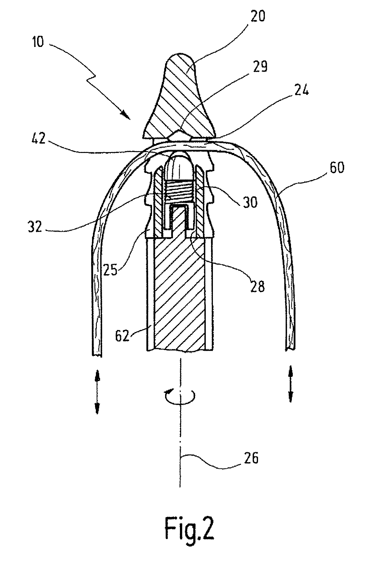
[0025] This can be done directly by the clamp element itself, or the clamp element can squeeze a further element, for example a clamping aid received in the transverse bore. Since the outside of the anchor element does not have to be covered during these movements, these maneuvers can be performed in the inside of the body after the anchor element has already been driven into the bone. In this way, it is also possible, for example, to correct the lie of the suture when the anchor element is already inserted, without the anchor element as such having to be moved relative to the bone for this purpose.
[0047] This is especially of help to the operating surgeon and facilitates this operating technique.

Problems solved by technology

This leads to additional and considerable outlay in terms of construction.

Method used


Image

  • Anchor Element For Knotless Fixing Of Tissue To A Bone
  • Anchor Element For Knotless Fixing Of Tissue To A Bone
  • Anchor Element For Knotless Fixing Of Tissue To A Bone

Examples


Embodiment Construction

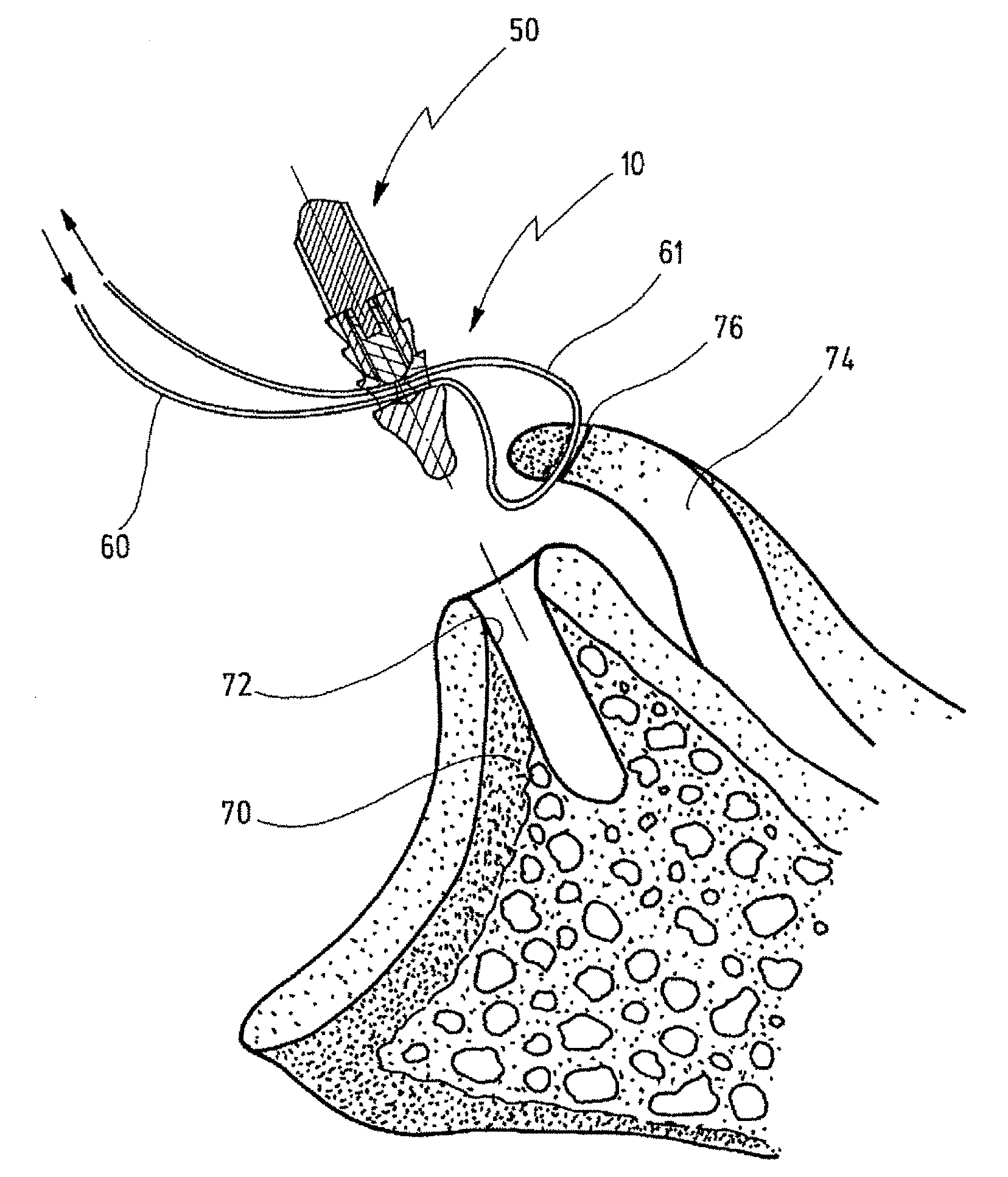
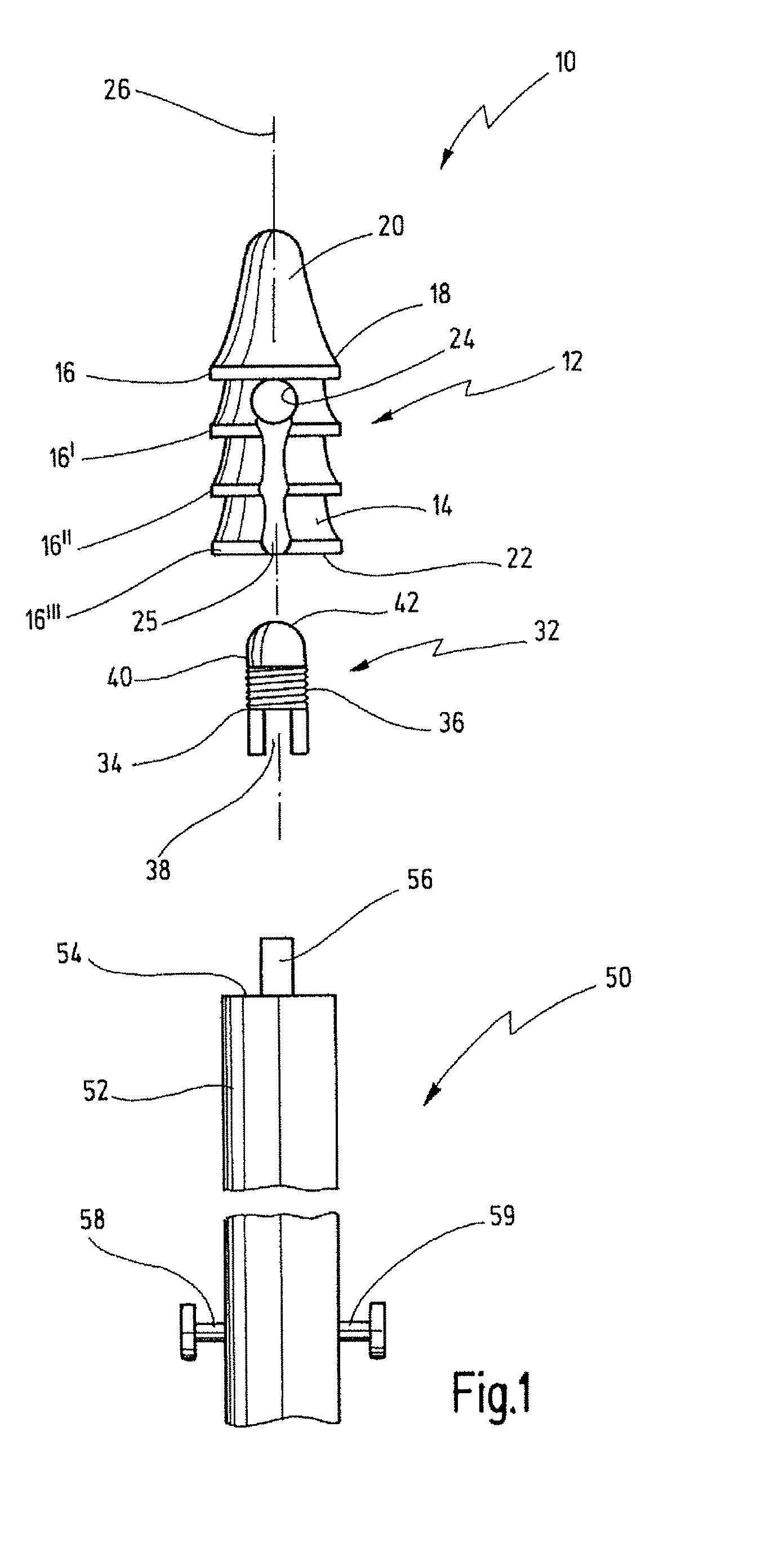
[0056] An anchor element shown in FIGS. 1 to 4 is designated in its entirety by reference number 10.

[0057] The anchor element 10 has an elongate, roughly cylindrical body 12 from whose outer face 14 a number of projections 16 to 16′″ protrude. The projections 16 to 16′″ are designed as protruding annular flanges which, viewed in the distal direction, each merge with the next annular flange via approximately conically tapering portions. A distal end area 18 of the body 12 is provided with a rounded tip 20. A proximal end 22 is formed by the cross-sectional surface area of the last projection 16′″.

[0058] In the distal end area 18 of the body 12, a transverse bore 24 is arranged extending through the latter. Starting from the mouth of the transverse bore 24, two diametrically opposite longitudinal grooves 25, cut into the projections 16′ to 16′″, extend proximally along the longitudinal axis 26 of the body 12.

[0059] The transverse bore is used for threading a suture 60 through the b...


PUM


Abstract

An anchor element serves for knotless fixing of a tissue to a bone by means of at least one suture threaded through said anchor element. A body of that anchor element has an outer surface with projections. A transverse bore is arranged in a distal end section of said body for receiving a threading passing therethrough. A clamp element serves for clamping the suture threaded transversely through the bore. The clamping element has a portion arranged within the body and is movably within the body towards that transverse bore.

Description

BACKGROUND OF THE INVENTION [0001] The invention relates to an anchor element for knotless fixing of tissue to a bone by means of at least one suture threaded through the anchor element. [0002] Generally, such anchor elements, also called suture anchors, are used in the medical field to ensure that tissues, mostly tendons, that have become detached from a bone can be fixed back onto the bone. [0003] For this purpose, the anchor element and a suture connected to the anchor element are driven firmly into the bone. The protruding suture ends are connected to the detached tissue, by which means the detached tissue is fixed to the bone. [0004] In a first operating technique, known in particular from U.S. Pat. No. 5,690,676, the anchor element is designed such that it has an approximately cylindrical body on whose outer face there are projections that prevent removal of the anchor element after it has been inserted into the bone. These projections can be designed as barb-like elements, fo...

Claims


Application Information

Patent Timeline
IPC IPC(8): A61B17/58
CPCA61B17/0401A61B17/0487A61B2017/0412A61B2017/0414A61B2017/0454A61B2017/0438A61B2017/045A61B2017/0453A61B2017/0427A61B2017/0409A61B2017/0446A61B2017/0448
Inventor GERBER, CHRISTIANMEYER, DOMINIKBERBERICH, SASCHA
Owner KARL STORZ GMBH & CO KG
Learn More