Multi-temperature programming for accelerometer

Active Publication Date: 2007-09-06
MEMSIC
View PDF5 Cites 40 Cited by
  • Summary
  • Abstract
  • Description
  • Claims
  • Application Information

AI Technical Summary

Benefits of technology

[0014] By testing and calibrating a plurality of integrated sensor devices such as integrated convective accelerometers in parallel at one or more probe stations using a

Problems solved by technology

However, the outputs produced by such accelerometers can vary over temperature, thereby reducing the overall accuracy of the accelerometers.
One drawback of the above-described technique for calibrating the output offset of an integrated convective accelerometer is

Method used


Image

  • Multi-temperature programming for accelerometer
  • Multi-temperature programming for accelerometer
  • Multi-temperature programming for accelerometer

Examples


Embodiment Construction

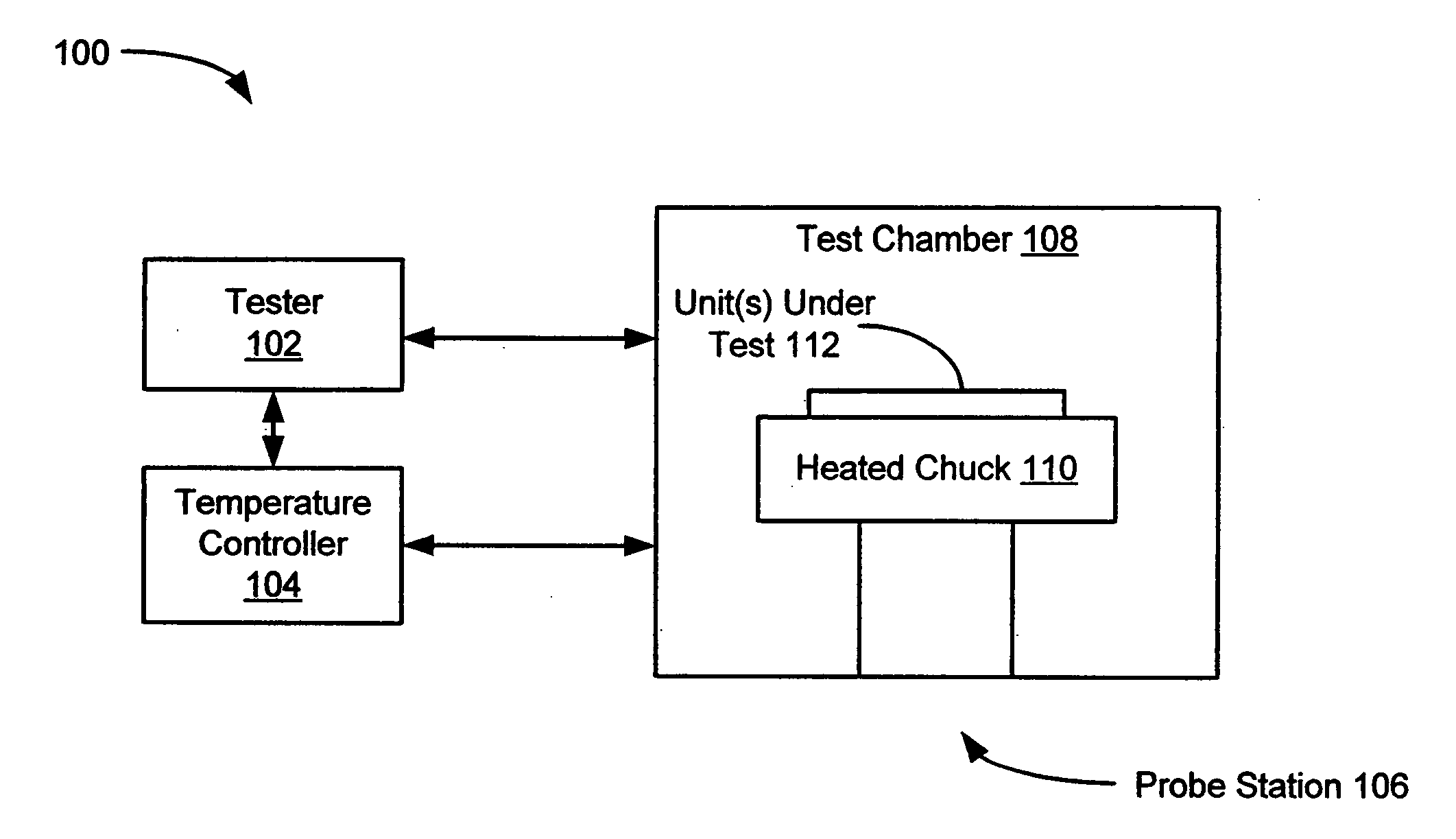
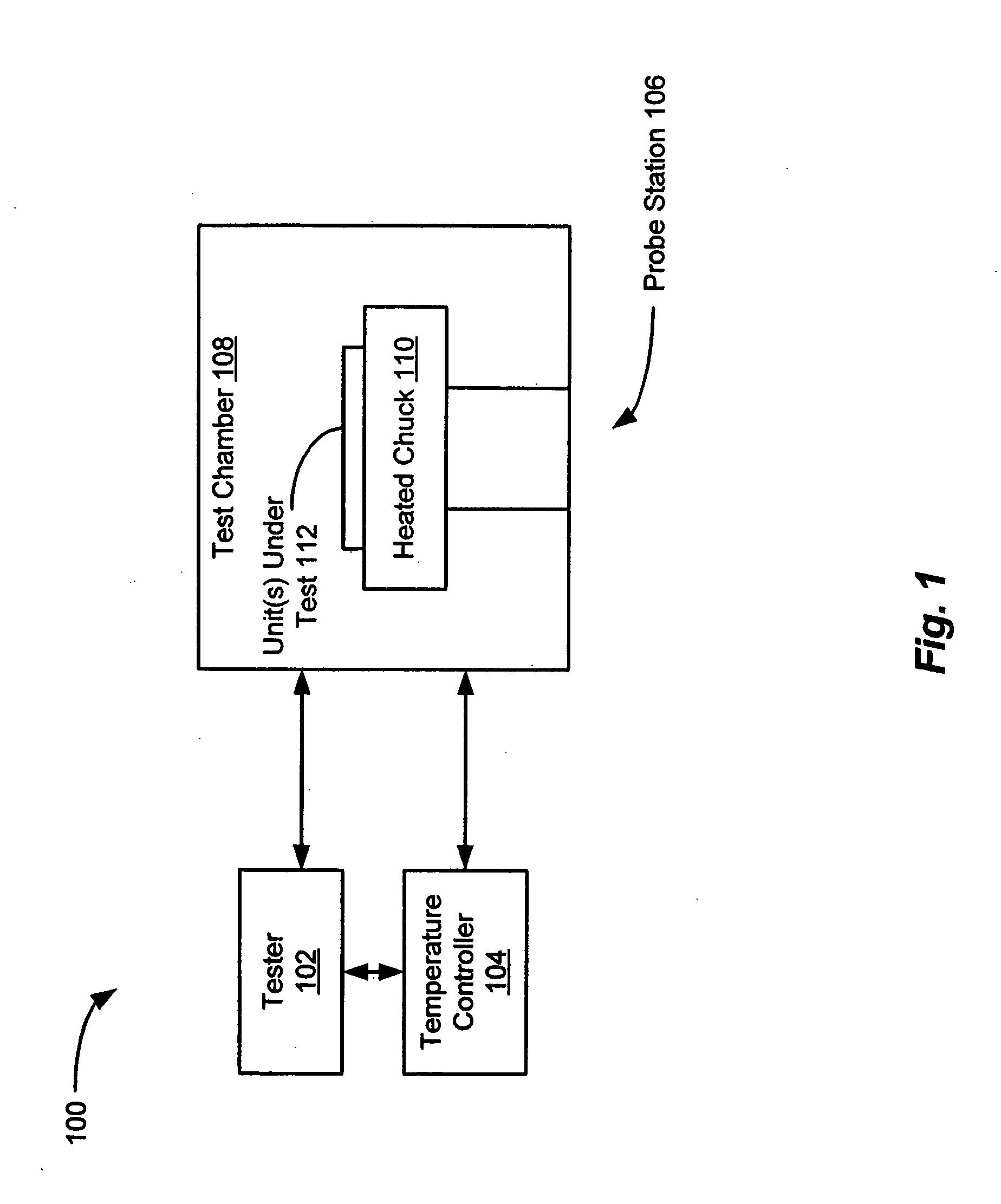
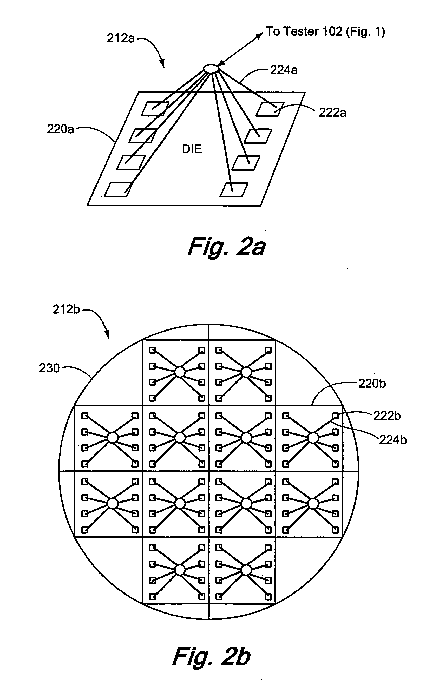
[0024] A system and method of testing and calibrating integrated sensor devices such as integrated convective accelerometers is disclosed that improves the manufacturing test throughput of the sensor devices. The presently disclosed system allows a plurality of integrated sensor devices to be tested in parallel at one or more probe stations. In the event the integrated sensor devices under test have one or more device parameters that are temperature dependent, multiple sensor devices may be tested at a first temperature using a first probe station, and may subsequently be tested at a second higher temperature using a second probe station. Alternatively, such integrated sensor devices may be tested at multiple temperatures at a single probe station using a variable temperature chuck. The presently disclosed system and method may also employ multiple oven chambers during the testing of integrated sensor devices to improve the overall manufacturing test throughput of the devices. The p...


PUM


Abstract

A system and method for testing and calibrating integrated sensor devices that improves the manufacturing test throughput of the devices. The system includes a tester, a temperature controller, and at least one probe station including a thermal chuck. The chuck can be heated to specified temperatures to achieve variable heating of a wafer, PCB, or pallet disposed thereon. The temperature controller adjusts the temperature of the chuck to a first specified level. The tester performs at least one first measurement of the output offset of each integrated sensor embodied as a die on the wafer, or as a device on the PCB or pallet. Next, the temperature controller adjusts the temperature of the chuck to a second specified level, and the tester performs at least one second measurement of the output offset of each integrated sensor at the second temperature level. The offset temperature coefficient (OTC) of each sensor is calculated based upon the output offset measurements performed at the first and second temperature levels, and optimal settings for calibrating the respective sensors are determined based upon the calculated OTC values. After the temperature of the chuck is brought back down to the first specified level, the tester programs the output offset calibration settings into each sensor.

Description

CROSS REFERENCE TO RELATED APPLICATIONS [0001] N / A STATEMENT REGARDING FEDERALLY SPONSORED RESEARCH OR DEVELOPMENT [0002] N / A BACKGROUND OF THE INVENTION [0003] The present invention relates generally to accelerometers, and more specifically to techniques for improving the manufacturing test and calibration throughput of integrated convective accelerometers. [0004] U.S. Pat. No. 6,795,752 entitled THERMAL CONVECTION ACCELEROMETER WITH CLOSED-LOOP HEATER CONTROL issued Sep. 21, 2004 and assigned to the same assignee of the present invention (the “'752 patent”) discloses an integrated convective accelerometer comprising a convective acceleration sensor that includes a pair of temperature sensing elements disposed on opposing sides of a heater element. When an acceleration is applied to the integrated convective accelerometer along a sense axis passing through the heater element and the pair of temperature sensing elements within the convective acceleration sensor, the sensor produces ...

Claims


Application Information

Patent Timeline
IPC IPC(8): G01R17/14
CPCG01P21/00G01P15/008
Inventor HUANG, FEIMINGLIU, HAIDONG
Owner MEMSIC
Why Eureka
Try Eureka